Global high-mix volume high-speed PCBA manufacturer
9:00 -18:00, Mon. - Fri. (GMT+8)
9:00 -12:00, Sat. (GMT+8)
(Except Chinese public holidays)
Global high-mix volume high-speed PCBA manufacturer
9:00 -18:00, Mon. - Fri. (GMT+8)
9:00 -12:00, Sat. (GMT+8)
(Except Chinese public holidays)
HomePage > Blog > Knowledge Base > How to Repair PCBs: A Complete Tutorial
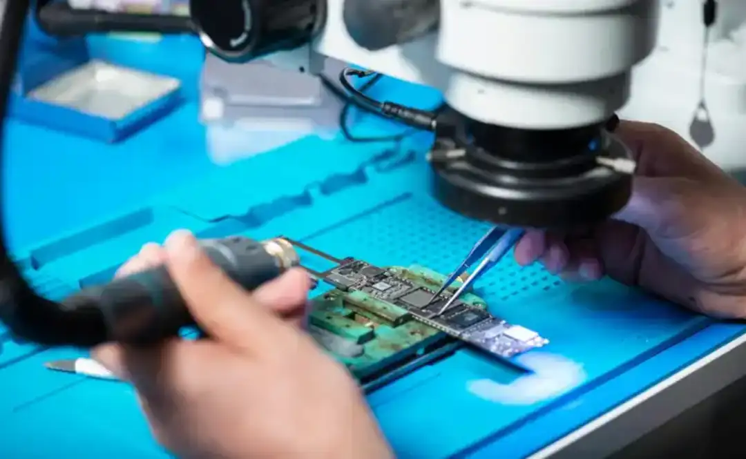
Printed Circuit Boards (PCBs) are used in nearly every industry, such as consumer electronics, the aerospace industry, the medical industry, the smartphone industry, and many more. PCBs function as the basic building blocks of an electronic system that connect everything to work together. However, sometimes these boards fail to perform or stop working due to various reasons such as overheating, old components, and mechanical damage. Despite the damage to circuit boards, the good news is that we can fix them. Fixing the damage to PCBs and making them work again is known as PCB repair. Repairing them will not just save the cost of replacing the entire board, but also save time. In order to repair your damaged PCB, you need skills, knowledge, tools, and techniques that help you to repair your PCBs. In this article, we will help you up your PCB repair skills, get you familiar with a PCB repair tool kit, and techniques so that you can repair PCBs and make them work again.

Almost all electronic devices you encounter in your daily life have a printed circuit board in it. The purpose of a circuit board is to make the device capable of doing the task it is intended to do. Every electronic device in your home, such as laptops, smartphones, and computers, has PCBs embedded in it.
For example, when your smart LED circuit boards function properly, you enjoy using them. However, when the circuit boards of these devices were damaged, they did not perform the intended task, and you could not watch your favorite TV show. To make them function again, circuit board repair comes into play. To repair such devices, repair skills, necessary tools, and knowledge are required. To get started with circuit board repair, it is important to understand the PCB structure and common causes of failures.
Designing the circuit board products is a complex task that requires expertise and knowledge. Especially when it comes to multilayer boards, we can divide the structure of PCB into the following basic parts.

1. Substrate
The substrate in circuit boards is a chemical material that is used as a base material. This material is commonly fiberglass or polyimide because it has good mechanical strength. It also provides electrical insulation and stability to circuit boards. FR-4 is a commonly used material in circuit boards as a substrate because it has good mechanical strength, stability, and reliability. However, selecting the substrate material is entirely application specific because, for low-power devices, FR-4 is a good choice, but for thermal applications, FR-4 may not be a good choice.
2. Copper Traces
When you see a circuit board, you only see the green part, but beneath is a network of copper traces. These copper traces on the circuit board are the signal pathways between the components to deliver the current. The width and thickness of copper traces decide how much current it can carry.
3. Vias
In multilayer circuit boards, vias are the drill holes that serve the function of electrically connecting the different layers. For example, when we need to take the track from the top layer to the bottom, we need to make a via to connect the top-layer track with the bottom layer.
4. Solder Mask
Solder mask is the color you see on the circuit board. It is usually green, red, or blue. This insulated color is embedded on the circuit board to protect the copper traces under it.
5. Silkscreen
The labels on the different components, like IC, resistors, and capacitors on the circuit boards, are silkscreen. These are the designators of the components to identify them.

When it comes to the circuit boards, there are numerous causes that contribute to circuit board failures. However, there are some of the most common failures that often occur in circuit boards. Understanding these common causes of failure and their occurrence reasons helps technicians to quickly identify the failures and repair the circuit board. Some of the common failures of circuit boards are
1. Broken Traces
Broken traces are a commonly occurring circuit board failure. They happen when the copper trace breaks, and it stops the supply of current to components. This causes the circuit board failure, and it must be repaired to restore the circuit board's health. Usually, broken traces occur due to mechanical stress and overheating. It can also happen due to manufacturing defects.
2. Damaged Vias
As you know now, vias are the drill holes that are used to make the electrical pathway between circuit board layers. Sometimes, these vias are damaged, and thus the electrical pathway between layers stops, resulting in circuit board failure. This can be repaired by filling the via with solder. Its causes include overcurrent and drilling defects.
3. Burn Marks
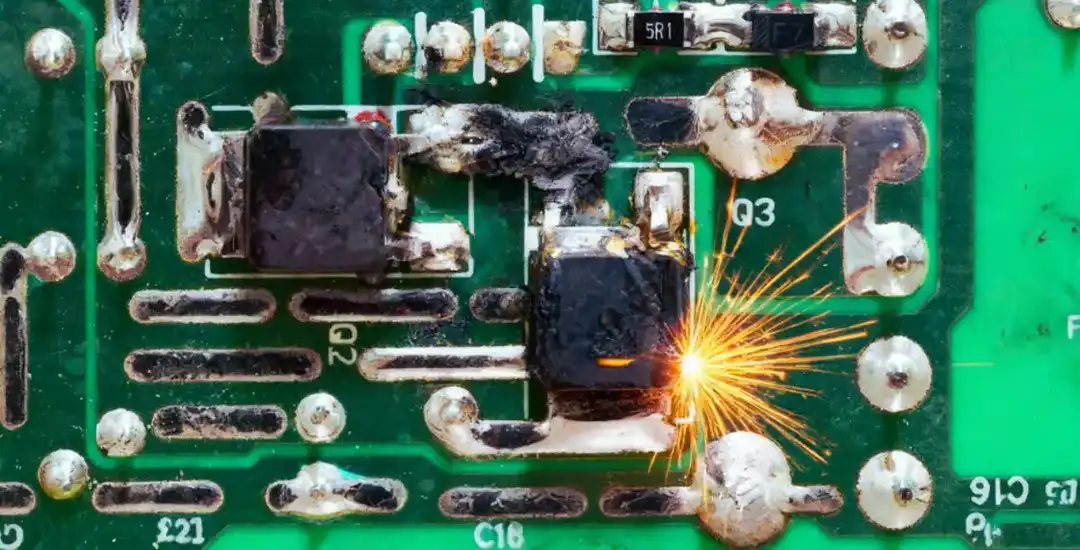
When a component or an IC experiences overcurrent, it is damaged. The component burns and leaves a mark that can be easily identified. These failures usually occur due to a short circuit and overcurrent. The repair of such failures often requires component replacements.
4. Corrosion
Corrosion often happens due to the chemical degradation of copper and solder. Corrosion mostly happens due to humidity and moisture.
5. Solder Joint Failures
When the solder joint between the lead and pad cracks, it results in solder joint failures. This failure is easy to repair and is mostly due to poor soldering and mechanical stresses.
In the coming section, I will explain how to repair these common circuit board issues.
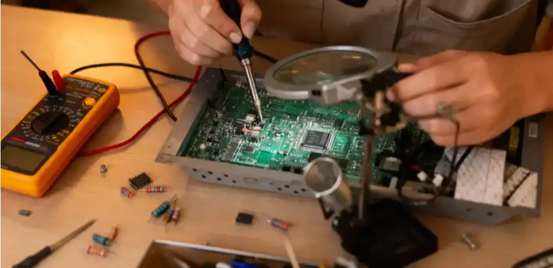
Circuit board repairs require not just skills but also the necessary tools and materials. For effective and efficient repair of circuit boards, tools and materials are essential, such as a soldering iron, a multimeter, a heat gun, solder wire, flux, and a repair kit.
1. Essential Tools
There are certain tools that are essential in circuit board repair. If one or more of these tools are not available, the repair cannot be effective.
• Soldering Iron: The most important repair tool is a soldering iron, along with a rework station. A soldering iron will help the repair technician to remove the damaged component from the circuit board. It also helps to make the solder joints.
• Digital Multimeter: A Multimeter is one of the most frequently used repair devices in circuit boards. A multimeter helps in continuity tests between tracks, helps check the short circuit tests by measuring the resistance, helps in identifying solder joints, and performs the voltage tests on different test points (TPs) in circuit boards.
• Magnifying Glass: This is another important tool in circuit board repair for identifying the micro defects in the circuit board, e.g., short circuits between the pins of the IC and lifted IC pads.
• Heat Gun and Tweezers: In circuit board repair, a heat gun is used in reflow soldering and component desoldering. Tweezers are used to carefully handle the tiny electronic components.
2. Repair Material
Circuit board repairing is not just about acquiring the tools; it also requires access to specialized repair material such as solder wire and flux.
• Solder Wires and Flux: Solder wires and flux are used together when making solder joints or installing the components on circuit board pads, such as resistors and capacitors.
• Copper Foil and Jumper Wires: Copper foil and jumper wires are used in circuit repair when the traces are broken.
• Epoxy and Adhesives: In some cases, the component pad has been lifted from the circuit board due to multiple component replacements. To repair such pads, epoxy and adhesives are commonly used.
3. Safety Precautions
Circuit boards can fail even with all tools and materials, if safety precautions are not properly followed. Circuit boards are sensitive to electrostatic discharge, known as ESD. Electrostatic discharge, if not properly handled, can cause the component without even knowing it. It is therefore recommended to properly follow the safety precautions. Always work or repair circuit boards with ESD protection, and wear protective glasses to avoid direct eye contact with soldering fumes.

Time is money in your projects – and PCBasic gets it. PCBasic is a PCB assembly company that delivers fast, flawless results every time. Our comprehensive PCB assembly services include expert engineering support at every step, ensuring top quality in every board. As a leading PCB assembly manufacturer, we provide a one-stop solution that streamlines your supply chain. Partner with our advanced PCB prototype factory for quick turnarounds and superior results you can trust.
Circuit board repairing is the second step, while the first step is to diagnose the damage to the circuit board. In this section, I will elaborate on a step-by-step guide to diagnose the PCB damage.
1. Visual Inspection
In the first step, make a visual inspection of the circuit board. Look for any burn signs, broken traces, and damaged solder joints. While visual inspection using a magnifying glass will allow you to see the microcomponents. For example, modern microcontrollers are smaller in size and have many pins. A magnifying glass helps you see the pins of such ICs to know if there are any lifted pads or short circuits between pins.
2. Continuity Testing
Continuity testing is beneficial in tracing out the circuit board defects. Using a digital multimeter and setting it to continuity mode will help you trace out the discontinuity between tracks, components, and vias. Continuity testing is one of the most frequently used tools in identifying circuit board damage. Checking the resistance between tracks helps the technician identify whether the track is connected or broken.
3. Thermal Checks
Another method to diagnose the damage in the circuit board is using thermal checks. Sometimes, due to the wrong connections, the ICs or components heat up abnormally, indicating an underlying short circuit. To identify that specific heat spot or component, thermal checks are performed using infrared cameras or thermographs.
4. Component Isolation
Sometimes nothing works, and that's where component isolation works. In this method, we disintegrate the components that are suspected. One by one, disintegrate the components from the board and then perform the individual testing. Sometimes, the damaged resistor causes a short path. Unplugging it from the board eliminates the short circuit error. Once the error is identified, circuit board repair techniques are used to restore the board's functionality.
With an all-in-one circuit board repair tool kit and materials, one cannot efficiently repair a circuit board until you have a solid grip on repair techniques. In this section, I will explain some of the most effective circuit board repair techniques to help you restore your circuit boards.

1. Trace Repair
Among all, broken traces are one of the commonly encountered faults. To repair such traces, the copper wire bridge method is used. In this method, an insulated wire is soldered between the two points to restore the electrical connectivity between joints and repair the circuit board.
2. Pad and Via repair
IC pads are damaged when they are removed with the wrong techniques or due to extreme mechanical stress. Pads can also be damaged or lifted when the component on that pad is removed many times. To repair such damages, a copper foil is used with epoxy to secure the pad. However, if the vias are damaged, usually solder is used to fill the hole.
3. Component Replacement
Sometimes, the issue does not lie with the circuit board damage but within the faulty components. If, for some reason, faulty components are used in the circuit board, the final circuit board will not work. In that specific scenario, the only solution is to identify such a component and replace it with a correctly functioning component. But care must be taken when the component is disintegrated to replace it with a new one.
|
Best Practice |
Explanation |
|
Use proper tools |
Always use a professional soldering iron, multimeter, and other tools. |
|
Control Heat application |
Apply heat precisely to components, excessive heat can damage components, vias, and pads. |
|
Follow ESD |
Always use grounded tools, wrist straps, and mats for circuit board repair. |
|
Stress Testing |
Once repair of circuit board is done, perform stress testing to ensure reliability. |
|
Factor |
When Repair Makes Sense |
Replacement is Better |
|
Cost |
Printed circuit board repair is cost effective |
For low value electronics, buying new one is better |
|
Tools & Skills |
When you have access to soldering station, and professional PCB services available |
Without advance tools repair is impractical |
|
Reliability |
Broken traces and capacitors, often repair with long term success |
Repairing destroyed boards is impractical |
|
Application Value |
Medical, aerospace, and automotive |
Consumer electronics, and low-cost board not worth to repair |
In conclusion, PCB repair is one of the most vital skills that help the industries to restore the circuit boards without replacing them with new boards. It will not only reduce the cost but also save time. Understanding the circuit board repair requires essential tools like a circuit board repair kit, soldering iron, a heat gun, a multimeter, and materials such as solder wire and flux. With these tools and materials, technicians with skills and knowledge can easily identify the circuit board defects and repair them.

Assembly Enquiry
Instant Quote
Phone contact

+86-755-27218592
In addition, we've prepared a Help Center. We recommend checking it before reaching out, as your question and its answer may already be clearly explained there.
Wechat Support

In addition, we've prepared a Help Center. We recommend checking it before reaching out, as your question and its answer may already be clearly explained there.
WhatsApp Support

In addition, we've prepared a Help Center. We recommend checking it before reaching out, as your question and its answer may already be clearly explained there.
