The miniaturization of
electronic devices is advancing rapidly. Signal integrity, system cost,
and reliability are becoming major challenges for engineers. To meet the
ever-growing requirements of the miniaturization of electronic devices, the rigid-flex
PCB solution is becoming popular.
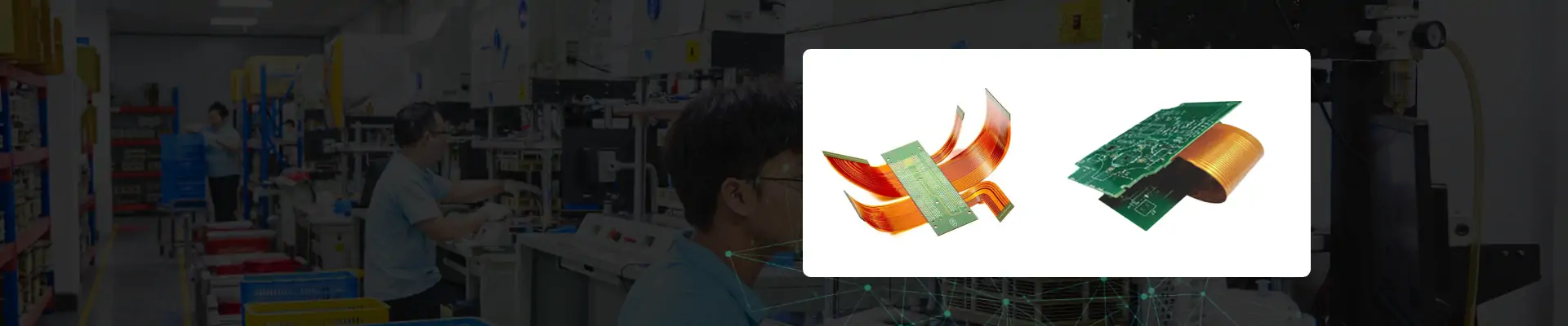
As the name implies, flexible circuit boards
introduce flexibility and bendability in electronic boards. The terms “rigid”
and “flex” imply that the circuit board has rigid and flex regions, making them
suitable for a wide range of applications, particularly in aerospace and military
applications. The use of flexible circuit boards eliminates the traditional
wiring connections. The flexibility and bendability of circuit boards are
primarily made using polyimide material instead of FR4, which is used only in rigid
PCBs. The flexibility of these circuit boards allows them to fit into complex
shapes and spaces, making them ideal for military applications, aerospace,
wearable electronics, cameras, and smartphones.
This article will help you to
understand and learn the rigid-flex PCB manufacturing process, its design, and
cost considerations. Whether you are an expert or a beginner, this guide will
ready you to kick-start your rigid-flex PCB.
What is a Rigid-flex PCB?
Rigid-flex PCBs are a type of circuit board that combines the
advantages of both rigid and flex circuit boards and offers a high level of
bendability and tensile strength. This makes them a popular choice in
applications such as medical devices, military applications, aerospace, cameras,
and smartphones. Their flexibility gives the user the freedom to fit them in
complex packaging geometry with precision and accuracy.
Mostly, polyimide
material is used to achieve flexibility. The polyimide material
properties offer a higher degree of flexibility as compared to the standard FR4
material, which is used in traditional rigid PCBs. The dielectric constant, or
simply Dk value, of polyimide material, is between 3.0 and 3.5, which is
better compared to FR4 material, which has 3.5 and 4.0. Commonly
used polyimide materials for rigid-flex PCBs are Nelco and Rogers. For only
flex PCBs, Kapton is generally preferred.
The rigid-flex PCBs are generally categorized into single-sided
rigid-flex PCBs, double-sided rigid-flex PCBs, and multilayer rigid-flex PCBs.
1. Single-Side Rigid-flex
PCB: The single-sided rigid-flex PCB is the basic
among all types. These circuit boards consist of a single conducting layer on a
flex substrate. Holes are drilled through the substrate to enable the
components to pass through during the soldering process. A coverlay made from polyimide
is commonly used to protect the circuit board from the harsh environment.
2. Double-Side Rigid-flex
PCB: These rigid-flex circuit boards consist of two
conducting layers. The plated through holes are drilled to make the electrical
connection between layers.
3. Multilayer Rigid-flex
PCB: Unlike a double-sided rigid-flex PCB, a
multilayer rigid-flex PCB consists of more than two conducting layers. The
Plated Through Holes (PTH) are drilled to make the electrical connections
between multilayers. These circuit boards are complex in design compared to
other rigid-flex PCBs, but they are considered an effective solution in
situations where crosstalk issues, high component density, and impedance
requirements are desired.
About PCBasic
Time is money in your projects – and PCBasic gets it. PCBasic is a PCB assembly company that delivers fast, flawless results every time. Our comprehensive PCB assembly services include expert engineering support at every step, ensuring top quality in every board. As a leading PCB assembly manufacturer, we provide a one-stop solution that streamlines your supply chain. Partner with our advanced PCB prototype factory for quick turnarounds and superior results you can trust.
Benefits of Rigid-flex PCBs
Rigid-flex PCBs have many unique benefits over traditional rigid
PCBs. These circuit boards are designed to fit into complex geometries and to
achieve a high degree of reliability.
1. Rigid-flex boards
are often used in military applications where they must
withstand harsh environmental conditions. The polyimide material used in
rigid-flex boards covers the conductors and protects the circuit board from
harsh environmental conditions.
2. Space becomes a
crucial factor in applications like aerospace and defense, where compactness
and lightweight are required. The rigid-flex PCBs’ ability to fit
into any shape enables them to save space and make them lightweight.
3. In
defense applications, circuit boards are more prone to high vibrational shocks,
like aircraft. Rigid-flex circuit boards’ ability to bend and flex enables them
to absorb high vibrational shocks.
4. As compared to
traditional rigid PCBs, rigid-flex PCBs can be reinstalled without being
damaged. Typically, a static rigid-flex PCB can be bending cycles or bent 100
times.
5. The rigid-flex
circuit boards give the designers creative freedom to make 3D shapes and many
different shapes. The different and complex shapes are often required in
applications like fitness equipment and wearable health monitoring equipment.
6. The ability of
rigid-flex PCBs to flex and bend without breaking enables them to absorb
mechanical and vibrational shocks. This makes them more reliable and durable
compared to traditional rigid circuit boards.
Rigid-flex PCB Applications
The modern electronics demand compact and smart devices that bring
the rigid-flex PCB into the game. The rigid-flex PCBs were initially used by the
military industry to make reliable and lightweight products. In current days, rigid-flex
PCBs are widely used in nearly every industry.
1. Medical Devices: Rigid-flex PCBs are used in medical devices that require compactness
and smartness, such as flexible sensors and wearable monitoring devices. Cardiac
devices are becoming sophisticated and smart, such as pacemakers. These devices
contain a flex circuit to achieve compactness, are lightweight, and are
reliable.
2. Consumer
Electronics: Rigid-flex PCBs are increasingly being
used in consumer electronics due to their ability to fit into complex spaces
like computers, laptops, smartphones, and cameras.
3. Aerospace Industry: The aerospace industry requires rugged, compact,
and lightweight devices that can survive the harsh environmental conditions. Rigid-flex
circuit boards fulfil these needs and are widely used in a wide range of
aerospace applications such as aircraft, drones, avionics, and space mission
devices. The NASA Mars rover also uses the rigid-flex circuit boards, which are
around 140 million miles away from Earth.
4. Military
Applications: Rigid-flex circuit boards are used in
military applications where space, weight, system reliability, and performance
are critical parameters, such as missiles, fighter jets, military radios, and
surveillance payloads.
5. Automotive
Industry: The advancements in the automotive
industry are increasing rapidly, such as the invention of automatic driving
cars. These advanced vehicles use rigid-flex circuit boards for their control
panels and internal wiring systems.
6. Robotics: The rise of AI and the development of autonomous and self-decision-making
robots demand a more reliable circuit board. The rigid-flex PCBs achieve
benchmarks to fit into complex spaces and are increasingly being used in the
field of robotics.
Design Considerations for Rigid-flex PCBs
When designing the rigid-flex PCBs, it is
important to carefully consider some design parameters such as bending radius,
thickness of material, and mechanical stresses, etc.
1. Calculate Bend Radius: It is important
to calculate the bend radius for your rigid-flex PCB to ensure flexibility
without damage. Bend radius is basically the measurement of the degree to which
a flex area of a circuit board can be easily bent. The correct calculation of
bend radius for your rigid-flex PCB ensures that the PCB can survive the
required number of bends.
Number of Layers
Bend Radius
1 or single side only
Thickness in mm x 6
2 or two-sided
Thickness in mm x 12
3 or multilayer board
Thickness in mm x 24
2. Number of Times
of Flexibility: Before starting the PCB design,
determine the number of times a PCB will be flexed. This gives you an idea of
whether you design a static rigid-flex PCB or a dynamic rigid-flex PCB.
3.It is recommended
to choose polyimide material for the flex part of the PCB and FR4 for the rigid
section.
4. It is
recommended that Plated Through Holes (PTH) should always be at least 0.5mm
away from the bend area.
5. Always avoid
90° of bending. The perpendicular pending can cause the board to break.
6. Do not use
Plated Through Holes on the flexible part or near the bending area of the flexible section.
7. Rigid-flex
PCBs are more prone to heat, and this can damage the PCB. So, proper thermal
management is important to avoid any overheating of the PCB.
8. PCB stack-up
plays an important role in determining the accuracy of the circuit board.
Multilayer Rigid-flex PCBs have more than two conductive layers. The proper
alignment of conductive layers ensures signal integrity and enhances overall
performance.
9. Proper
conductor alignment and adhesion between layers are essential to maintain
circuit integrity and performance while retaining maximum flexibility.
10. When
designing rigid-flex PCBs, always adhere to the IPC 6013 standard of rigid-flex
PCBs.
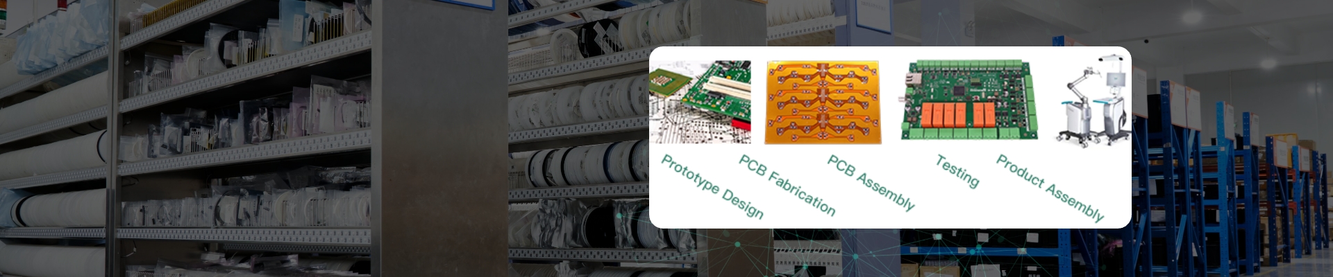
Manufacturing Process of Rigid-flex PCBs
Unlike
the fabrication of rigid PCBs, rigid-flex PCBs are complex and require careful
attention to prevent errors and achieve accurate flexibility. The key steps for
manufacturing rigid-flex PCBs are;
1. Schematic Design: In the first step, the PCB design engineer
designs the schematic of the rigid-flex PCB. The design engineer specifies all
the rigid and flexible parts in the schematic by following the IPC 6013
standard.
2. Material Selection: In this step, materials for both
the rigid and flexible parts are selected. Typically, polyimide or Kapton is
used for the flex part, and FR4 material is used for the rigid part.
3. Lamination Process: Both rigid and flexible parts of
the PCB are laminated under extreme temperatures such that the PCB achieves
strong mechanical bonding.
4. Drilling and Plating: Plated through holes are drilled
to create the electrical connections between the conducting layers of the
rigid-flex board.
5. Component Placement: Components are placed on the pads.
Solder paste is applied, and reflow soldering is performed to attach the
components to the board.
6. Final Testing and
Inspection: Finally,
using different inspection machines, testing is performed to identify any
errors or faults, if any.
Cost Considerations for Rigid-flex PCBs
The rigid-flex PCBs are expensive,
and there is no doubt about it. The initial cost of the rigid-flex PCBs is
higher due to the use of specialized materials, a unique manufacturing process,
and additional design considerations.
1. Rigid-flex Assembly Efficiency: The initial cost of these circuit
boards may be higher, but they reduce the connectors and cables that make the
assembly process easier. This enhances the overall efficiency of the assembly
process, which reduces labor costs and errors.
2. Cost Savings: The initial cost
of rigid-flex circuit boards is higher, but the long-term cost reduces due to
the reliability.
3. High Volume Production and Cost: One way to reduce the initial cost
of the rigid-flex boards is to increase the production volume. When the
production increases, the per-unit cost of fabrication decreases.
4. Prototype Development and Cost: The development is an iterative
process. In the prototype phase, design changes and modifications can hit the
overall budget of the product. It is important to consider these factors during
the planning stage to ensure cost-effective development of the product.
How do Rigid-flex PCBs differ from Traditional Rigid PCBs?
The rigid-flex PCB is a board that
has the ability to flex and bend. Their flexibility makes them ideal for
applications where size, space, and shape are critical. As the name implies,
the rigid-flex circuit board has both rigid and flexible parts. The rigid part
is made using FR4 material, and the flex part uses polyimide or Kapton material
to increase flexibility. The dielectric constant of polyimide material is much
better than FR4, making it ideal for the flex part of the PCB. Depending upon
the degree and use of flexibility, rigid-flex PCBs are classified as
single-sided, double-sided, and multilayer rigid-flex boards. These circuit
boards are mostly used in high-density interconnects, military applications,
and wearable electronics.
On the other hand, traditional
rigid PCBs do not have any flexible parts. They are primarily made with FR4
material. Unlike rigid-flex PCBs, rigid PCBs cannot absorb high vibrational
shocks and can be easily damaged. Their rigidity makes them unfit for complex
geometries.
Flex and Rigid-flex Overview
The flex and rigid-flex are both types of PCBs and are used for
unique purposes. The flex circuit boards can be flexed and bent without being
damaged. The flex circuit boards are used where lightweight, compactness, and a
smaller number of connectors are required. In flex PCBs, usually, polyimide or
Kapton material is used to achieve flexibility. The improved DK value of these
circuit boards enables them to achieve flexibility and bendability. Depending
upon the degree of flexibility and bendability, flex PCBs are categorized into
two types.
1. Static Flex PCBs: If a flex PCB is designed such that it can only be flexed less than
100 times in its lifetime. This type of flex PCB is called a static flex PCB.
The static flex PCBs are generally bent only during the assembly process. These
are not designed to flex after the assembly process. Once the circuit board is
fitted into the end product, it remains static.
2. Dynamic Flex
PCBs: If a flex PCB is designed such that it can be
regularly flexed is called as dynamic flex PCB. These circuit boards can
withstand thousands of cycles of bending.
On the other hand, rigid-flex PCBs combine
the advantages of both rigid and flex PCBs. In rigid-flex circuit boards, one
part of the PCB is rigid, which has all the components, and the other part is
flexible for providing the interconnection between the two rigid areas. Depending
on the type of application, either one or more flexible circuits are attached
to rigid boards. Rigid-flex PCB offers numerous advantages, including
flexibility, bendability, ruggedization, handling vibrational shocks, and
space-saving, making them ideal for applications like medical devices, defense,
wearable, and consumer electronics.
Difference Between FFC and FPC
The Flexible Flat Cable (FFC) is a simple cable that has wires at
both ends with no additional circuitry attached to it. They are primarily used
for interconnection between modules. On the other hand, Flexible Printed
Circuit (FPC) is a cable that has wires at both ends and additional circuitry
attached to it. It is more complex than FFC. Both FFC and FPC are designed for
special applications.
PCBasic: A Rigid-flex PCB Supplier from China
Selecting the right man for the
right job is always a critical task. When it comes to manufacturing rigid-flex
PCB, PCBasic is the trusted and reliable supplier. Here are the reasons you
should consider PCBasic for your rigid-flex design.
1. High-Quality Standards: We have comprehensive test and
control procedures that ensure quality checks at every
step of the production cycle. We are proud to have an ISO9001 and QS9000 quality system
to meet the international standards.
2. Competitive Pricing: Rigid-flex PCB is expensive, and
we know it. That is why we offer very market-competitive prices to our client
to maximize their profitability. We believe in making long-term
relationships.
3. Reliability: We are a leading rigid-flex PCB supplier in
China and across the border. Our technical team strictly follows the standards
and procedures to ensure the product meets with excellence. Our strict policies
prevent any use of incorrect components or parts, which makes the end product
reliable and durable. We have over 10 years of experience in PCBA manufacturing. We deliver rigid-flex circuit boards to our
clients that perform with accuracy and precision.
4. Technical Capabilities: Our technical team is capable of
handling your complex rigid-flex PCBs with ease. We have an expert team that is
capable of handling any issues that may arise in the fabrication process.
We use cookies to enhance your experience, analyze traffic, and provide personalized content. By clicking “Accept Cookies”, you agree to our Cookie and Privacy Policy.
Manage Cookie Preferences
We use cookies to enhance your browsing experience. Please review the details of each cookie category below and choose your preferences.
Strictly Necessary Cookies
These cookies are essential for the website to function properly and cannot be disabled. They are typically set in response to actions you take, such as logging in or adding items to your shopping cart.
Performance Cookies
These cookies help us understand how visitors interact with our website by collecting information about traffic and usage. This allows us to measure and improve the website’s performance.
Targeting/Advertising Cookies
These cookies are used to deliver
advertisements relevant to you and your interests. They may also limit the number of times you see an
advertisement and help measure the effectiveness of advertising campaigns.
In addition, we've prepared a Help Center.
We recommend checking it before reaching out, as your question and its
answer may already be clearly explained there.
✖
Wechat Support
In addition, we've prepared a Help Center.
We recommend checking it before reaching out, as your question and its
answer may already be clearly explained there.
✖
WhatsApp Support
In addition, we've prepared a Help Center.
We recommend checking it before reaching out, as your question and its
answer may already be clearly explained there.


 About PCBasic


