In the field of electrical and electronic engineering, there is a special form of communication language - electrical symbols. These shapes and diagrams, which correspond to specific meanings, are a globally accepted technical language in the electronics field. No matter which country or background you come from, we can communicate and convey information without ambiguity through this language.
Whether it is electrical schematic symbols, electrical wiring diagram symbols, or electrical component symbols, they can convey the function, direction and connection relationship of components in very small graphics. This method is much more efficient than textual description. If you are a beginner in the field of electronics, then you must first learn electrical symbols because these symbols are a compulsory and foundational course in this field. In this article, we will explain the relevant content of electrical symbols. After reading this article, you will have a complete basic electrical symbols chart as a reference and master the related knowledge.

What Are Electrical and Electronic Symbols?
Electrical and electronic symbols are standardized graphic representations used to visually depict electrical components, electronic devices, and functions in engineering drawings. They are a form of visual shorthand in the engineering field. They use concise, globally applicable symbols to replace lengthy textual descriptions, making the drawings more intuitive and easier to understand.
Specifically, electrical symbols and electronic symbols belong to the same electrical and electronic symbol system and follow the same international standards, but their typical application scopes are still different.

Electrical symbols are more commonly found in high-voltage power systems, wiring diagrams, and industrial control layouts. They are often used to represent circuit breakers, transformers, grounding points, and other components. While electronic symbols are mainly used in low-voltage circuits, PCB schematics, and signal processing circuits. They are often used to represent resistors, capacitors, diodes, transistors, and integrated circuits, etc.

Despite these differences, these two types of symbols overlap in many basic components. For example, resistors, capacitors, and diodes will appear in both electrical diagrams and electronic schematics.
Electrical Symbols, Electronic Symbols and Circuit Symbols
In the previous text, we introduced the connections and differences between electrical symbols and electronic symbols. Among them, there is another frequently mentioned concept, which is circuit symbols. Circuit symbols are often used in schematic diagrams to represent various components and functions in electrical or electronic circuits.

Overall, electrical symbols and electronic symbols are two major categories, with some overlap (such as resistors, capacitors, diodes, etc., which are used in both electrical diagrams and electronic circuit diagrams). While circuit symbols are a subset of electrical & electronic symbols. However, its scope is not the entirety of the intersection of the two, and there are also some parts that are exclusive to either electrical symbols or electronic symbols. As shown in the figure below,
Why Are Standardized Symbols Important?
The use of the standardized symbol system consisting of electrical symbols, electronic symbols and circuit symbols is not merely for convenience or aesthetics. It is also a fundamental requirement for ensuring safety, clarity and efficiency.

A unified symbol system can lead to clearer and more universal understanding. Unified and standardized electrical and electronic symbols ensure that engineers, technicians and designers from different countries can understand the same set of electrical diagram symbols without any obstacles. This common language can avoid misunderstandings caused by language or terminology differences and facilitates communication.
Consistent electronic and electrical symbols can also ensure design consistency. Each circuit symbol has a fixed meaning and appearance. This consistency guarantees that the interpretation method is always the same, whether in the basic electrical symbol chart or in complex electrical schematics.
The standardized symbol system can also enhance the efficiency of design and troubleshooting. With it, technicians can draw diagrams more efficiently and troubleshoot problems more quickly. The points mentioned earlier mainly pertain to the advantages during the design stage. However, the standardized symbol system does not only offer advantages at the design level. Its benefits extend throughout the entire lifecycle of the project. It helps global technicians create professional documents, reduces error rates, and enhances safety. Whether it is a single circuit diagram (electrical circuit diagram) or a multi-layer PCB schematic, the standardized symbols can be applied.
How to Read and Understand Electrical Symbols?
Standardized symbol systems are of great importance. So how should we master the methods for reading electrical schematic symbols and electrical circuit symbols? Here are the methods we have summarized, which can be helpful for quickly and accurately understanding the drawings.

1. Each basic electrical symbol is composed of three parts: shape, direction, and label.
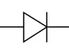
The shape usually indicates the function of the component. For example, resistors are commonly represented by zigzag lines or rectangles in different standards, while diodes are indicated by an arrow pointing to a vertical line. These shape features can help engineers quickly identify the type of component in electrical schematic symbols.
The direction is often found in electronic symbols with signal flow or current direction. For instance, the arrow direction of transistors and diodes indicates the path of current or signal flow.
Labels are also an indispensable part of the drawing. Usually, beside each symbol, there will be a label indicating the component's number (such as R1, C3, U5) and the component's parameter values (such as 10kΩ, 100nF). This labeling method facilitates a quick search for corresponding information in the electrical symbol chart or bill of materials.
2. Although it was mentioned earlier that the electronic symbol system is unified and standardized, different countries and industries may follow different standards. Therefore, it would be best for us to be familiar with several common standards:
IEC: The most widely adopted international standard globally, covering the vast majority of electrical diagram symbols.
ANSI: The most commonly used standard in the United States, with slight differences in symbol shapes compared to the IEC standard.
ISO: Covers electrical symbols in the industrial field and is often combined with mechanical, architectural, and other fields.
Suggestion: Regardless of which standard is used, it is best to establish a unified standard at the beginning of the project to ensure consistency throughout the design, production, and maintenance processes.
3. When understanding, we can proceed step by step, from simple to complex. We can first master the common components in the basic electrical symbol chart, such as resistors, capacitors, power symbols, and grounding symbols. These symbols form the basis of all electrical circuit symbols. After proficiently grasping these basic symbols, we can gradually expand to more complex electronic schematic symbols, such as operational amplifiers and microcontrollers.
Symbols Chart
Previously, we introduced the definitions, differences and connections of electrical symbols, electronic symbols and circuit symbols. Below are the most common and frequently mentioned symbols of these three types, along with standard symbol examples and explanations.
Electrical Symbols
|
Category
|
Symbol Name
|
Description
|
Symbol Image
|
|
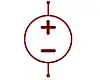
Power & Ground
|
DC Power
|
DC supply terminal, marked +V, Vcc, or +5V
|
|
|
AC Power
|
AC supply terminal, often with voltage/frequency
|

|
|
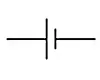
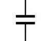
Battery
|
Multiple cells providing a DC voltage
|

|
|
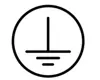
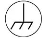
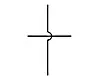
Earth Ground
|
Ground connection for safety/signal reference
|
|
|
Chassis Ground
|
Ground connected to equipment chassis
|
|
|
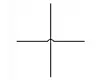
Connection & Wiring
|
Straight Wire
|
Electrical conductor
|

|
|
Junction
|
Connection point (solid dot)
|

|
|
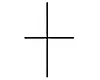
No Connection
|
Wires crossing without connection
|
|
|
Switches & Protection
|
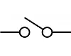
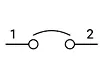
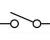
SPST Switch
|
Single-pole single-throw (on/off)
|
|
|
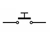
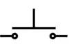
Push Button (NO)
|
Normally open momentary switch
|
|
|
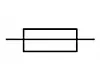
Fuse
|
Overcurrent protection device
|
|
|
Circuit Breaker
|
Resettable protection device
|
|
|
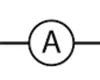
Measurement Instruments
|
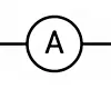
Ammeter
|
Measures electric current
|
|
|
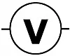
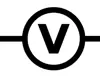
Voltmeter
|
Measures voltage
|
|
Electronic Symbols
|
Category
|
Symbol Name
|
Description
|
Symbol Image
|
|
Passive Components
|
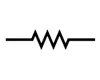
Resistor
|
Limits current; zigzag (IEC) or rectangle (ANSI)
|

|
|
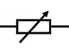
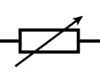
Variable Resistor
|
Adjustable resistance
|
|
|
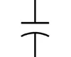
Capacitor (Non-polarized)
|
Stores electrical energy; no polarity
|
|
|
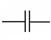
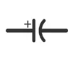
Capacitor (Polarized)
|
‖
|
|
|
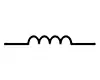
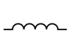
Inductor
|
Stores magnetic energy
|
|
|
Semiconductors
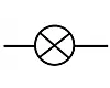
|
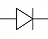
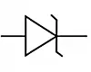
Diode
|
Allows current in one direction only
|
|
|
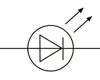
LED
|
Light-emitting diode
|
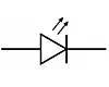
|
|
Zener Diode
|
Voltage-regulating diode
|
|
|
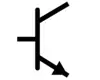
NPN Transistor
|
Bipolar junction transistor (NPN)
|
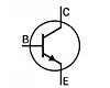
|
|
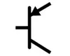
PNP Transistor
|
Bipolar junction transistor (PNP)
|
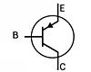
|
|
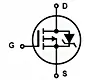
MOSFET (N-Channel)
|
Field-effect transistor, N-channel
|
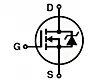
|
|
MOSFET (P-Channel)
|
Field-effect transistor, P-channel
|
|
|
Output & Display
|
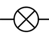
Lamp
|
Light-emitting device for illumination
|
|
|
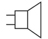
Speaker
|
Produces sound
|
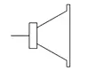
|
|
Buzzer
|
Audio alert/alarm
|
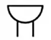
|
|
7-Segment Display
|
Digital numeric display
|
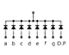
|
|
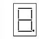
LCD Display
|
Liquid crystal display module
|
|
Circuit Symbols
|
Category
|
Symbol Name
|
Description
|
Symbol Image
|
|
Power & Ground
|
DC Power
|
DC voltage source in circuits
|
|
|
AC Power
|
AC voltage source
|

|
|
Battery
|
Multiple cells providing DC
|

|
|
Earth Ground
|
Ground reference
|

|
|
Connection
|
Wire (Connected)
|
Junction where wires connect
|
|
|
Wire (Not Connected)
|
Wires crossing without connection
|
|
|
Passive Components
|
Resistor
|
Fixed resistor
|
|
|
Variable Resistor
|
Adjustable resistor
|
|
|
Capacitor (Non-polarized)
|
Capacitor without polarity
|
|
|
Capacitor (Polarized)
|
|
|
|
Inductor
|
Inductor coil
|
|
|
Semiconductors
|
Diode
|
One-way current device
|
|
|
LED
|
Light-emitting diode
|
|
|
Transistor (NPN)
|
BJT transistor, NPN type
|
|
|
Transistor (PNP)
|
BJT transistor, PNP type
|
|
|
Switches
|
SPST Switch
|
On/off switch
|
|
|
Push Button (NO)
|
Normally open button
|
|
|
Output Devices
|
Lamp
|
Light source
|
|
|
Speaker
|
Audio output
|
|
|
Measurement
|
Ammeter
|
Measures current
|
|
|
Voltmeter
|
Measures voltage
|
|
Application of Electrical & Electronic Symbols

In the early days of electrical engineering, different regions and industries adopted different symbol styles. This led to frequent misunderstandings when reading electrical diagram symbols from other countries or companies. Over time, organizations such as IEC and ANSI began to promote the global standardization of circuit symbols and electronic symbols. As a result, we have an internationally recognized basic symbol system, allowing engineers from one country to read electrical wiring diagram symbols from different countries without any difficulties.
Electrical symbols and electronic symbols are almost ubiquitous in modern engineering. When drawing electrical schematic symbols, designers can replace lengthy textual descriptions with standardized graphics, making the entire drawing more intuitive and easier to understand.
In fields such as building power distribution and industrial wiring, electrical wiring diagram symbols are used to indicate information such as power sources, grounding, wire connections, switches, circuit breakers, etc. This helps construction workers accurately complete wiring during installation. These symbols also play a very important role in equipment renovation and maintenance. Maintenance personnel can quickly locate fault points based on common electrical symbols, avoiding incorrect connections or omissions.
In the field of electronic design, electronic symbols are an indispensable part of PCB schematic diagrams. When engineers draw circuits, they use circuit symbols to represent components such as resistors, capacitors, inductors, diodes, transistors, integrated circuits, etc., and combine them with basic electrical symbols to establish a complete circuit logic. This approach not only facilitates PCB design and production but also saves a lot of time in subsequent testing and fault troubleshooting.
In daily engineering practice, electrical circuit symbols are applied throughout the entire process of design, manufacturing, installation, commissioning, and maintenance. From the drawing in the design stage to the assembly in the production stage, and to the fault troubleshooting in the maintenance stage, these symbols always serve as the bridge for engineering communication. They not only serve large industrial projects but are also widely present in household appliances, automotive electronics, communication equipment, and other products.
Conclusion
Electrical symbols, electronic symbols and circuit symbols constitute an engineering "universal language" that transcends languages and geographical boundaries. These simple and standardized graphics carry complex technical information. From design drawings to production assembly, and to subsequent maintenance and repair, they always serve as the bridge for efficient communication among engineers. It can be said that proficient mastery of these symbols is the prerequisite for ensuring precise, safe and efficient design.
In global engineering collaboration, the basic electrical symbols chart is not merely a reference manual; it is also the foundation for all parties' collaborative work. Only by correctly understanding and applying common electrical symbols can the design be more rigorous and the subsequent fault detection and resolution be more efficient. Electrical and electronic symbols are not merely markings on the drawings; they are the key link that turns technical concepts into safe, reliable and long-term stable electrical and electronic systems.
 About PCBasic
Time is money in your projects – and PCBasic gets it. PCBasic is a PCB assembly company that delivers fast, flawless results every time. Our comprehensive PCB assembly services include expert engineering support at every step, ensuring top quality in every board. As a leading PCB assembly manufacturer, we provide a one-stop solution that streamlines your supply chain. Partner with our advanced PCB prototype factory for quick turnarounds and superior results you can trust.