Global high-mix volume high-speed PCBA manufacturer
9:00 -18:00, Mon. - Fri. (GMT+8)
9:00 -12:00, Sat. (GMT+8)
(Except Chinese public holidays)
Global high-mix volume high-speed PCBA manufacturer
9:00 -18:00, Mon. - Fri. (GMT+8)
9:00 -12:00, Sat. (GMT+8)
(Except Chinese public holidays)
Remove the smartphone and car images from your mind for a second. Can you think of a society that does not have access to them? No, right? So, what is the backbone of these devices? It’s the tiny PCBs which are doing all the things for you! In all types of PCBs, rigid PCBs, as the name suggests, are the most effective ones due to their longevity, stability, and capacity to manage multifaceted circuits. A rigid PCB board is a solid PCB prototype that does not bend and is usually made up of fiberglass (FR4) or other materials which do not change shape with stress or heat. Such rigid boards are essential in wide-ranging applications from consumer electronics to industrial equipment. Now, let us delve into the construction and manufacturing process of rigid PCBs, their advantages and uses to grasp what underpins their overwhelming prominence in the electronic box assembly.
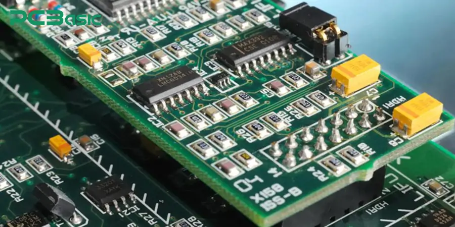
A rigid printed circuit board, or rigid PCB, is constructed using a solid substrate which does not allow bending. It is meant to hold its form permanently to provide a stable base for container assembling, electromechanical interfacing, and physical securing. Unlike flex PCBs, which can be reshaped and folded, rigid PCBs can be relied upon for mechanical strength and structural integrity over time. Thus, they are best suited for devices needing a stable backbone.
Most rigid PCBs are made from fiberglass (FR4) or other rigid laminates, which are reinforced with epoxy resin. Chemical and thermal strengthening processes make these materials more resistant to heat, chemicals, and stress. Fiberglass serves as the core of most rigid PCBs. Furthermore, electronic components such as resistors, capacitors, and chips are added to create the desired flow of electricity between components.
The reliability of a rigid PCB is dependent on the box assembly and the interaction between its layers. And what are those layers? Let’s have a look at them.
The structure of a Rigid PCB starts from the substrate layer. It provides strength and rigidity to the PCB assembly. A substrate is customarily constructed using fiberglass reinforced epoxy, more popularly known as FR4. The “substrate” in the substrate layer of the PCB prototype gives it strength and serves as the “backbone” of the rigid PCB.
Then, the rigid board is brought to life with electrical box build connections occurring in the copper layer. It enables the signals and power to flow between various parts and components of the board. After preparing the substrate, which mainly consists of the polymer FR4, a thin foil of copper is laminated onto rigid circuit boards.
The third layer is the solder mask, which is usually visible at the top and is green in color. It does give rigid boards an aesthetic look, but primarily, it serves as a protective solder cover to prevent soft copper traces from short-circuiting during the soldering process.
Lastly, the silkscreen layer binds everything together, providing details to the box build assembly. It has a “topographical representation” and includes its components, such as logos, to make identification for the manufacturers and engineers easy during the box assembly and troubleshooting.
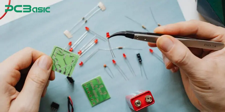
Well, all rigid PCBs are not made equally, but they have different forms and types, which makes them suitable for different applications. Let’s explore them.
Single-sided PCBs are the most basic type of rigid PCB. They have only a single layer of copper on each side of the substrate. They are inexpensive and simple to produce, making them suitable for low-density applications. These include basic electronic devices, calculators, and LED lights.
Double-sided PCBs have copper layers on both sides of the substrate, therefore with them more complex circuits can be made. Both sides can have components and connections, allowing for more intricate designs. These are often utilized in control systems, amplifiers and even industrial equipment.
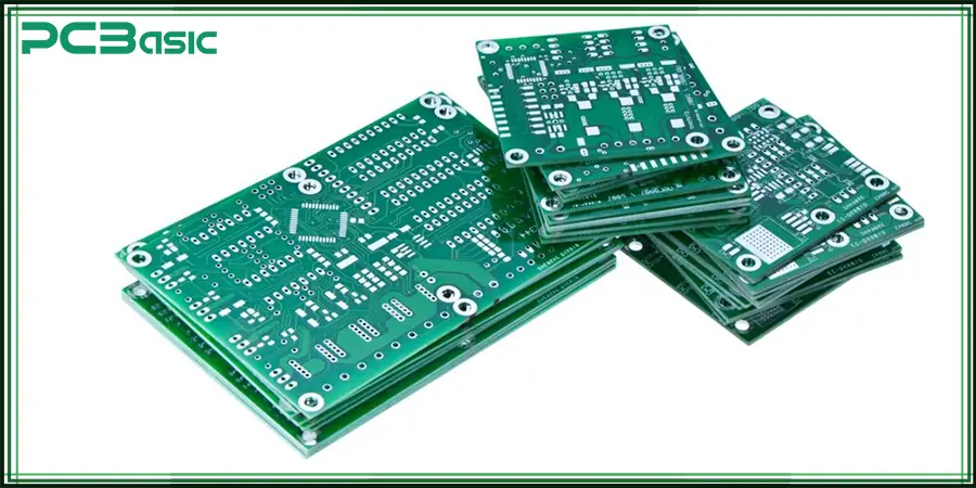
Multilayer PCBs are used in advanced technological designs, like medical devices or smartphones. It comprises three or more stacked copper layers intertwined with insulating material.
Heavy copper rigid PCBs have added applications compared to standard PCBs. Usually, normal PCB prototypes have a more difficult time handling high electrical currents, mechanical stress, and even visceral strain. However, heavy copper rigid PCBs withstand this much more easily.
High-Tg PCB gets its name from the glass transition temperature (Tg). High-Tg rigid PCBs withstand the highest of temperatures, sustaining over 170 °C. They are used in automotive and aerospace electronics as these applications need to withstand extreme heat.
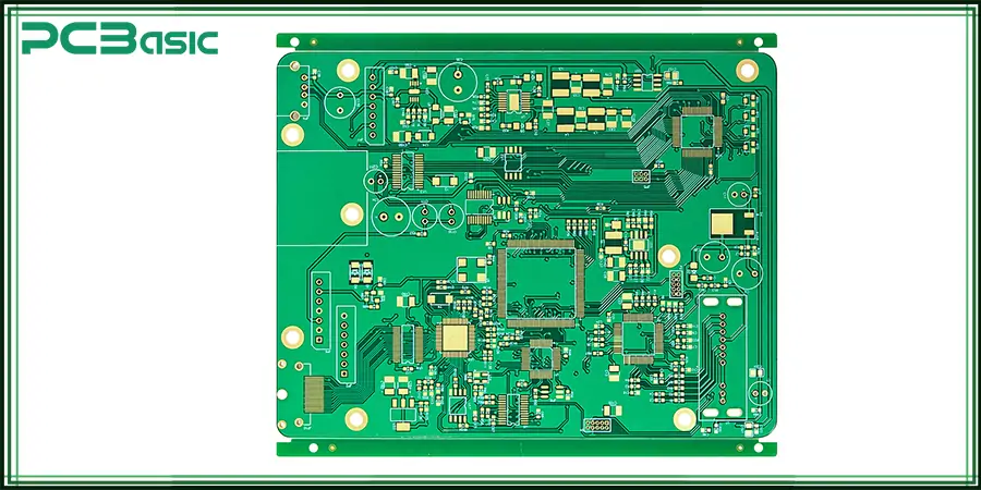
Anything that needs to work with very high signal frequencies uses high-frequency rigid PCBs. These PCBs are specially made from low-loss substrates, like PTFE (Teflon), so they can provide minimal signal loss and reliable electrical function.
Rather than utilizing fiberglass substrates, MCPCBs use a metal base, commonly aluminum or copper, increasing thermal management. They are perfect for LED lighting systems, power supplies, high high-power automotive electronics because of MCPCBs.
Let us walk you through the steps on how we at PCBasic manufacture rigid PCBs.
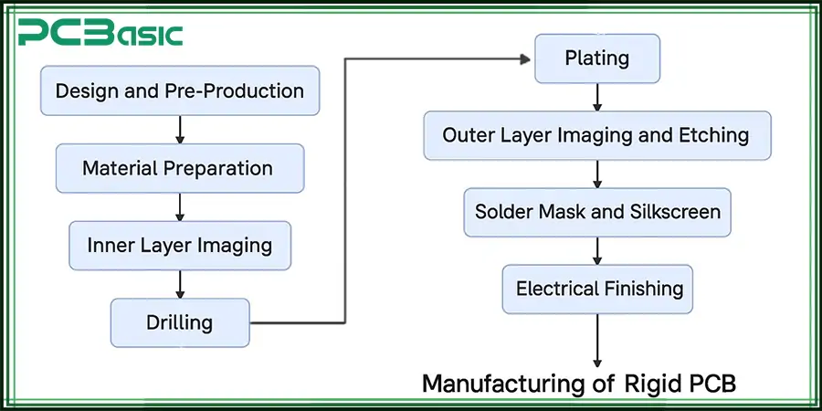
1. To begin with, our team does initial PCB layout along with a manufacturability review, which uses specific design rules to catch errors before they escalate.
2. The next step involves cutting and cleaning the FR4 sheets or other similar substrates.
3. Copper foil is coated with photoresist and exposed to UV light to define the circuit pattern.
4. After that, copper foil, along with other insulating materials, is heated and pressed together to form the rigid board.
5. Later, our team uses precision drills or lasers to create holes for vias and component leads.
6. Both left and right sides are etched to take away excess copper
7. A protective coat or mask is added to cover the circuit board, which in turn prevents exposure to a short circuit.
8. Lastly, silkscreen printing is used to directly print inscriptions, such as labels, logos, and numbers, onto the surface of the board, making it easier to identify.
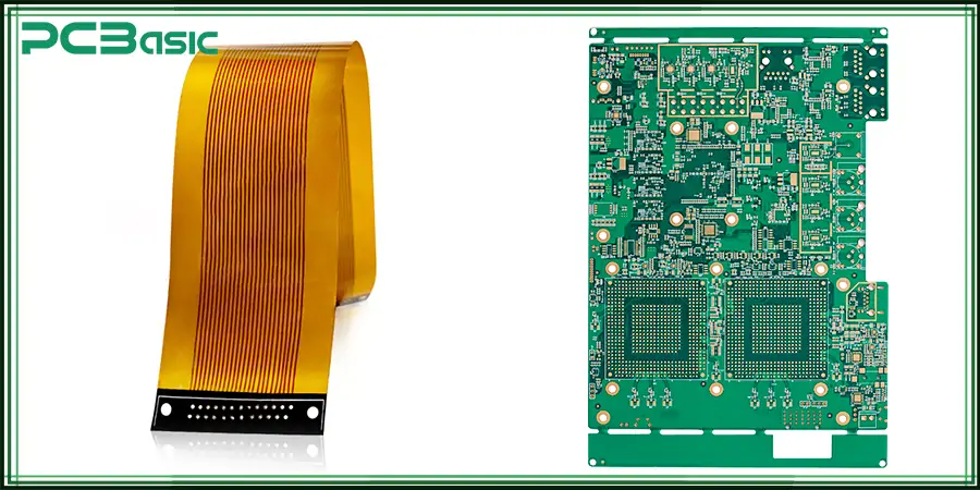
There’s been a long debate on rigid PCB vs. flex PCB, and a lot of you are confused about which one is better. So, let’s break down things for you. Rigid PCBs are constructed on solid substrates such as FR4, which provides high mechanical strength, considerable dimensional stability, as well as they are appropriate for multilayer, high-density configurations. Some examples include computers, automotive systems, and industrial controls.
On the other hand, flex PCBs employ a polyimide base, which is more flexible and thus allows folding and bending of the circuits without breakage. They are critical for lightweight and compact designs where size limitations and dynamic movement are crucial, such as in the medical field, aerospace, and integrated electronics. The decision to choose rigid and flex PCBs is mainly influenced by mechanical and environmental space constraints.
Rigid PCBs have been relied on for their mechanical strength and electrical performance, as well as unmatched long-term durability. These features and advantages of rigid PCBs make them the go-to choice for numerous electronic devices and applications
Some features of rigid PCBs are listed below.
Rigid PCBs are made from durable materials like fiberglass (FR4), preserving the shape permanently. They do not bend or flex, which aids in maintaining a steady platform for fragile electronics box build.
Rigid boards can have multiple-layer circuits, which allows complex routing along with dense component placement without signal degradation.
Medical instruments, smartphones, and tablets are compact devices which require rigid PCBs, they offer tolerances during production, resulting in accurate fitting.
Now, let’s explore some of the benefits of rigid PCBs.
Rigid PCBs are known to endure for several years and in harsh environments, all thanks to their underlying rigid PCB material. This also leads to improved product dependability and reduced lifetime replacement costs.
Rigid boards are produced at a lower cost and are highly beneficial for various applications, especially when made in large quantities. Unlike other PCB prototypes, rigid PCBs undergo streamlined fabrication processes, which enable quicker production time.
Automation in soldering and assembly is compatible with rigid printed circuit boards (PCBs), streamlining box build assemblies and ensuring uniform quality.
Rigid PCBs, as discussed earlier, have a wide range of applications. Here are some its top industries.
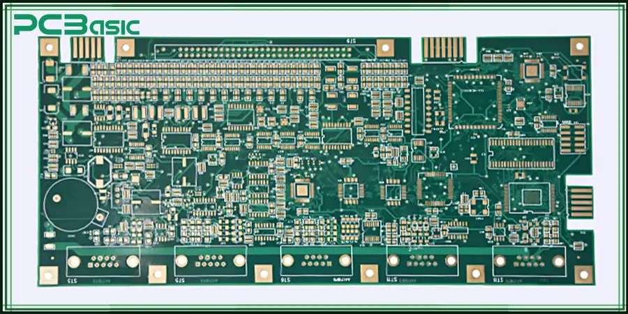
Rigid PCBs are the backbone of a computer’s motherboard, providing a stable and durable platform to support critical components like the CPU, RAM, GPU, and storage connectors. Their multilayer design enables the efficient routing of complex circuits while maintaining signal integrity and mechanical strength.
They are widely used in everyday electronics, including smartphones, televisions, and ovens. They provide a strong, reliable structure that keeps all the tiny components in place, ensuring devices work smoothly even with constant use.
With the advent of new automobiles, PCBs are completely indispensable. Rigid boards are used to control the steady flow of high electrical signals in sophisticated systems like Electric Vehicles (EVs) and Advanced Driver Assistance Systems (ADAS).
Rigid PCBs are crucial in all modes of communication, radio systems, mobile phones, routers and satellite systems. They ensure communication is carried out smoothly with minimal signal disruption.
The manufacturing process of rigid PCBs goes beyond simply getting a working board. The quality, dependability, and effectiveness must meet international standards and best practices. In this case, the IPC has set certain standards for PCBs. IPC-A-600 and IPC-6012 are among the most widely recognized standards. “IPC-A-600 lists the visual and physical appearance standards for rigid PCBs, highlighting the areas of acceptance and defect for each layer and finish.” IPC-6012 specifies the performance, material, and testing issues for certifying rigid boards to meet the demands of clients in the aerospace, automotive, and telecommunications industries, ensuring that the boards are capable of withstanding real-world mechanical and environmental strains.
Meeting IPC standards entails strict QC control for the production processes. Major checks include micro-sectional cuts, AOI shattered glass checks, shorts, and open-circuit electrical tests. Adhering to these steps enables the manufacturer to claim that every rigid PCB is not only designed to operate in the provided conditions but also assures sustained performance and structural integrity over decades.
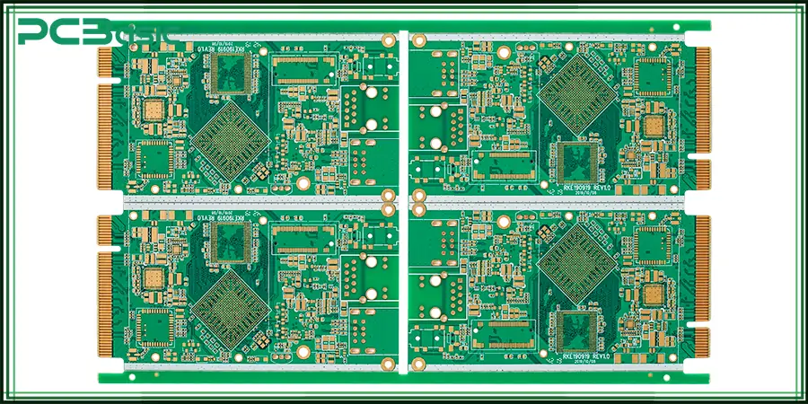
PCBasic with its advanced manufacturing and quality control techniques customizes single, double and multilayer boards using FR4, high-Tg, or metal-core materials. Each PCB is manufactured to the standards of IPC-A-600 and IPC-6012, ensuring reliable performance for diverse applications, including consumer electronics, industrial automation, aerospace, and more. So, if you’re also looking for a reliable supplier of rigid PCBs, contact us today!
Rigid PCBs are essential in today's technology, from everyday appliances to complex industrial systems. Their strength, dependability, and accuracy make them an industry favorite. Therefore, as the electronics industry continues to evolve, rigid PCBs will always be the cornerstone.
Time is money in your projects – and PCBasic gets it. PCBasic is the pcb assembly company that delivers fast, flawless results every time. Our comprehensive PCB Assembly Services include expert engineering support at every step, ensuring top quality in every board. As a leading PCB Assembly Manufacturer, we provide a one-stop solution that streamlines your supply chain. Partner with our advanced PCB Prototype Factory for quick turnarounds and superior results you can trust.
Assembly Enquiry
Instant Quote
Phone contact

+86-755-27218592
In addition, we've prepared a Help Center. We recommend checking it before reaching out, as your question and its answer may already be clearly explained there.
Wechat Support

In addition, we've prepared a Help Center. We recommend checking it before reaching out, as your question and its answer may already be clearly explained there.
WhatsApp Support

In addition, we've prepared a Help Center. We recommend checking it before reaching out, as your question and its answer may already be clearly explained there.
