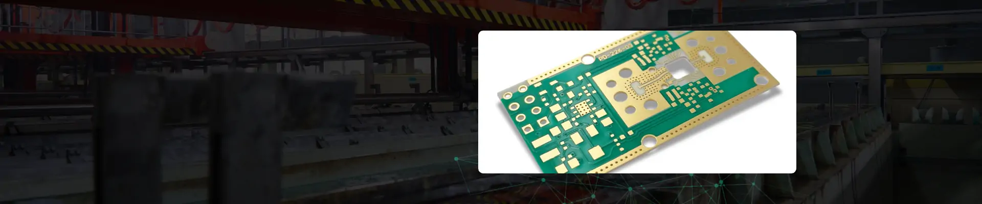
What Is a Rogers PCB?
With the development of electronic technology, the
production of electronic products requires more and more materials, such as
high-frequency materials.
Take Rogers PCB as an example. Rogers
PCB material is a kind of high-frequency board produced by Rogers Company,
which is different from conventional PCB board epoxy resin. It has no glass
fiber in the middle and is a ceramic-based high-frequency material. When the
operating frequency of the circuit is above 500MHz, the range of materials
available to design engineers is greatly reduced.
Rogers PCB material has excellent dielectric constant
and temperature stability, and its thermal expansion coefficient of dielectric
constant is very consistent with that of copper foil, which can be used to
improve the shortcomings of PTFE polytetrafluoroethylene substrate. It is very
suitable for high-speed design, as well as commercial microwave and RF
applications.
Because of its low water absorption, it can be used as
an ideal choice in high humidity environment, providing customers in
high-frequency board industry with the best quality materials and related
resources, and fundamentally controlling product quality.
Generally speaking, Rogers PCB high frequency board can
be defined as PCB printed circuit board with frequency above 1GHz. Its physical
performance, accuracy and technical parameters are very demanding, and it is
often used in communication systems, automobile anti-collision systems,
satellite systems, radio systems and other fields.

The Classification of
Rogers PCB Board Material Series
Rogers PCB board material RO3000®
series:
Based on ceramic-filled PTFE circuit
materials, the models are RO3003G2™, RO3003™, RO3203™, RO3035™, RO3006™,
RO3010™, RO3210™ Rogers PCB board material RO4000® series: Ro4000
ceramic-filled hydrocarbon laminate and prepreg is a leading product series in
the industry. The models include: RO4003C, RO4350b, RO4360G2, RO4830, RO4835T,
RO4533, RO4534, RO4535, RO4725JXR and RO4730G3.
Rogers PCB board material RT/duroid®
Laminate:
RT/Duroid® high-frequency circuit
material is a composite laminate containing PTFE filler (random glass fiber or
ceramic), which is suitable for high reliability, aerospace and national
defense applications. Include: RT/duroid® 5880, RT/duroid® 5880lz, RT/duroid®
5870, RT/duroid® 6002, RT/duroid® 6202, etc.
Rogers PCB board material TMM® series:
Composite materials based on ceramics,
hydrocarbons, and thermosetting polymers, model numbers: TMM3, TMM4, TMM6,
TMM10, TMM10i, and TMM13i. etc.
Detailed Analysis of
Rogers PCB Parameters
1. Rogers
PCB board substrate has low water absorption, and high-water absorption will
cause dielectric constant and dielectric loss when it is wet.
2. The
thermal expansion coefficients of Rogers PCB board substrate and copper foil
must be consistent, otherwise, the copper foil will be separated during the
change of heat and cold.
3. The
dielectric loss (Df) of Rogers PCB board substrate material must be small,
which mainly affects the quality of signal transmission. The smaller the
dielectric loss, the smaller the signal loss.
4. The
dielectric constant (Dk) of Rogers PCB board substrate must be small and
stable. Generally speaking, the smaller the better; the signal transmission
rate is inversely proportional to the square root of the dielectric constant of
the material. The high dielectric constant is easy to cause signal transmission
delay.
At present, the global 5G layout is accelerating.
Traditional 3G/4G base station distributed architecture can be divided into
BBU, RRU, and antenna feeder systems, in which RRU and antenna feeder systems
are connected by the feeder. As the risk of transmission loss increases with
high frequency, the architecture of integrated RRU and antenna feeder systems
can reduce the signal loss on the feeder and improve transmission efficiency.
The high integration means that a large number of scattered components are replaced
by PCB boards, which ultimately increases the unit usage of PCB.

Some Rogers PCB Material
Properties
In rapid PCB prototyping, Rogers
PCB is a special circuit board with a certain technical threshold, which is
difficult to operate and high in cost. General PCB proofing factories are too
troublesome to make, or because of the small number of customer orders, they
don't want to do it or rarely do it.
Rogers PCB RO4350B material allows RF
engineers to design circuits conveniently, such as network matching, impedance
control of transmission lines, etc. Because of its low dielectric loss, RO4350B
has more advantages than ordinary circuit board materials in high-frequency
applications. The fluctuation of its dielectric constant with temperature is
almost the lowest among similar materials. In a wide frequency range, its
dielectric constant is quite stable, 3.48, and the recommended design value is
3.66. LoPra™ copper foil can reduce insertion loss. This makes the material
suitable for broadband applications.
Rogers PCB RO4003 material can be
removed with a traditional nylon brush. Before electroplating copper without
electricity, no special treatment is needed. The board must be treated with a
traditional epoxy resin/glass process. Generally, it is not necessary to remove
the drilling hole because the high TG resin system (280°C+[536°F]]) does not
easily change color during the drilling process. If the stain is caused by
aggressive drilling operations, the resin can be removed by a standard CF4/O2
plasma cycle or double alkaline permanganate process.
The cooking requirements of RO4000
materials are equivalent to those of epoxy resin/glass. Generally, the
equipment that does not cook epoxy resin/glass plate does not need to cook the
RO4003 plate. For installing epoxy resin/baked glass as part of the conventional
process, we recommend cooking at 300°F, 250 F (121 C-149 C) for 1 to 2 hours.
RO4003 contains no flame retardant. It can be understood that boards packaged
in infrared (IR) units or running at a very low transmission speed can reach
temperatures in excess of 700 F (371 C). RO4003 can start burning at these high
temperatures. The system that still uses the infrared reflux device or other
equipment that can reach these high temperatures should take necessary
precautions to ensure that there is no risk.
RO3003 is a ceramic filled PTFE
composite for high frequency circuit materials, which is used in commercial
microwave and radio frequency applications. This series of products is designed
to provide excellent electrical and mechanical stability at competitive prices.
Rogers PCB Ro3003 material has excellent dielectric constant stability in the
whole temperature range, including eliminating the change of dielectric
constant when PTFE glass material is used at room temperature. In addition, the
loss coefficient of Ro3003 laminate is as low as 0.0013 to 10 GHz.
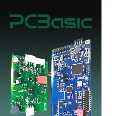 About PCBasic
Time is money in your projects – and PCBasic gets it. PCBasic is a PCB assembly company that delivers fast, flawless results every time. Our comprehensive PCB assembly services include expert engineering support at every step, ensuring top quality in every board. As a leading PCB assembly manufacturer, we provide a one-stop solution that streamlines your supply chain. Partner with our advanced PCB prototype factory for quick turnarounds and superior results you can trust.
What is FR4 Material?
Before deciding whether to choose FR4 or
Rogers PCBs, it is crucial to figure out what FR4 material is needed first. FR4
material is a very common substrate for circuit boards, which is made by
laminating fiberglass cloth with epoxy resin. Its greatest advantages are its
low cost and good mechanical strength, so it is widely used in various general
electronic products, such as computer motherboards and TV circuit boards.
However, when your circuit needs to transmit
high-frequency signals, FR4 material seems somewhat inadequate. Because its
dielectric constant changes with frequency, which leads to large signal loss
and performance degradation.
FR4 or Rogers PCB
Materials: Which One Should We Choose?
Here’s the
comparison table between FR4 dielectric material and Rogers PCB material,
showing differences in key properties, performance, and application
suitability:
|
Feature
|
FR4 Dielectric Material
|
Rogers PCB Material
|
|
Material
Composition
|
Fiberglass
+ epoxy resin
|
Ceramic-filled
PTFE or high-performance composites
|
|
Dielectric
Constant (Dk)
|
Around
4.2–4.8, varies significantly with frequency
|
Stable,
typically between 2.2–3.5, with minimal variation
|
|
Signal
Loss at High Frequency
|
Higher,
prone to signal attenuation
|
Very
low, ideal for high-frequency transmission
|
|
Performance
Stability
|
Moderate,
unstable at higher frequencies
|
Excellent,
maintains consistent electrical performance
|
|
Thermal
Performance (CTE)
|
Higher
expansion, prone to deformation under heat
|
Low
expansion, highly thermally stable
|
|
Manufacturing
Difficulty
|
Easy
to process, widely supported
|
Requires
specialized handling and equipment
|
|
Cost
|
Low,
ideal for mass-market, low-frequency electronics
|
Higher,
best for high-end or RF applications
|
|
Typical
Applications
|
Consumer
electronics, computers, general PCBs
|
5G
infrastructure, RF systems, radar, satellite communication
|
|
Hybrid
Stack-up Compatibility
|
Often
used in hybrid builds
|
Commonly
combined with FR4 for balanced cost and performance
|
When
choosing between FR4 dielectric material and Rogers PCB material, the most
important factor is where your circuit will be used:
FR4: If you're working on general-purpose,
low-frequency electronic products with a limited budget, then FR4 is already
good enough.
Rogers
PCB: But if your
circuit needs to handle RF signals, microwaves, or high-speed digital signals
(such as 5G communication or radar systems), it's better to use Rogers PCBs
because they offer more stable performance and lower signal loss.
Of
course, sometimes both materials can be used together — combining Rogers
circuit board material and FR4 dielectric material on the same board. This way,
you can ensure performance while also saving costs. It's a common approach in
many advanced applications.

Rogers PCB & PTFE
PCB: High-Frequency PCBs
In the fields of radio frequency (RF)
and microwave, the PTFE PCB (polytetrafluoroethylene PCB) is a very important
high-frequency circuit board. Its most outstanding features are extremely low
signal loss, strong transmission performance, and can withstand high
temperatures. So it is often used in some devices with high-performance
requirements, such as radars, satellite communications, 5G base stations,
high-frequency communication modules, etc.
Many high-quality Rogers PCB materials
are actually developed based on PTFE. For instance, Rogers' RT/duroid series
and RO3000 series all belong to PTFE PCBS. These materials can maintain a
stable dielectric constant in high-frequency environments, with very low signal
transmission loss, making them highly suitable for high-speed and RF circuits.
In contrast, traditional FR4 PCBs
perform less well at high frequencies: their dielectric constants are unstable
and signals are prone to attenuation, making it impossible to produce
high-performance products. So if you are working on high-frequency or
high-reliability projects, such as 5G or radar, it would be more appropriate to
choose Rogers circuit board materials or PTFE PCBs.
High-Frequency Band
Forces PCB Materials to Become High-Frequency
At present, the global 5G layout is
accelerating. Traditional 3G/4G base station distributed architecture can be
divided into BBU, RRU, and antenna feeder systems, in which RRU and antenna
feeder systems are connected by the feeder. As the risk of transmission loss
increases with high frequency, the architecture of integrated RRU and antenna
feeder systems can reduce the signal loss on the feeder and improve the
transmission efficiency. The high integration makes a large number of scattered
components replaced by PCB boards, which ultimately increases the unit usage of
PCB.
The 5G era must make use of the
high-frequency band (3GPP has specified that the frequency range supported by
5GNR is 450MHz-52.6GHz) because:
1. After the iteration of the first four generations of
communication technologies, the resources in the low-frequency band have been
occupied, and there are not many resources available for 5G development;
2. The higher the frequency, the more information can be
loaded, the richer the resources, and thus the higher the transmission rate
(for example, only five 20MHz channels can be divided in 100MHz, while 50 20MHz
channels can be divided in 1GHz). Due to the resonance phenomenon caused by
load and the influence of the transmission line effect, the higher the
frequency of electromagnetic waves, the more severe the attenuation will be.
To
realize efficient transmission at high frequency, it is necessary to control
the loss of signals on the transceiver and transmission devices, and the
corresponding bearing devices will be changed from ordinary plates in the past
to high-frequency plates (such as Rogers PCB RO4350 material). Specifically,
the terminal antenna originally used FPC (flexible printed circuit board) with
PI as the main material, but due to the dielectric constant (Dk, The ability of
medium to block electrons) and dielectric loss (Df, the ability of transmission
medium to convert electric energy into heat energy) are both high, so the
transmission efficiency is low. Therefore, the trend of replacing PI with
liquid crystal polymer (LCP) with lower Dk and Df is becoming increasingly
prominent.
At present, LCP has been introduced into Apple mobile phones, and
LCP materials are expected to become mainstream materials in the future. Taking
Apple as an example, the single LCP module in iPhone X is about 4-5
USD/antenna.
The base station also needs high-frequency
materials (such as Rogers PCB RO4350 material). At present, the mainstream
scheme is to use polytetrafluoroethylene (PTFE) or hydrocarbon PCB (with very
good dielectric properties). The unit cost is increased by about 1.5-3 times. A
high-frequency AC board is needed at the 3G/4G base station RRU. Among them,
high-frequency materials (such as Rogers PCB RO4350 material) are needed for
the PCB of RF power amplifiers. The demand for high-frequency (such as Rogers
PCB RO4350 material) PCB board for 5G AAU medium and high-frequency AC board
will increase, and the amount of high-frequency materials used in PCB board
will increase, thus increasing the value of a single board.

High-frequency PCB board is a special kind of
copper-clad laminate with high-frequency microwave substrate, also called
high-frequency microwave PCB board, which can be made into high-frequency PCB
by further processing. Rogers PCB board made of Rogers PCB high-frequency
material is widely used in communication base station and antenna aviation,
with high demand and promising market prospects.
As the world's leading supplier of
special plates, Rogers Board has a global market share of over 50%, and has 20
years of industry experience in the field of base station antenna radio
frequency. The company has set up a third R&D center in the United States,
focusing on the R&D of 5G products, and has launched a high-frequency board
for 5G antenna RF. With the expansion of the 5G commercial scale, the company
is about to usher in high-performance flexibility.
The market is aware that 5G has a large demand
for high-frequency boards, but it doesn't know that the biggest demand
elasticity is Rogers PCB board for base station antennas. As the frequency band
of the 5G application is higher than 4G, it is necessary to adapt to the Rogers
PCB board of millimeter wave, and the development trend of the antenna will
turn to multi-reception, multi-transmission, and miniaturization. The number of
antenna ports has increased from the traditional 4-port and 8-port to 64-port
and 128-port, and the demand for Rogers PCB board for antenna application has
increased dramatically.
After industry research, it is
conservatively estimated that the procurement cost of initialization materials
for a 5G antenna is 3-4 times that of a 4G multimode antenna, and the number of
Rogers PCB boards used in multi-receiver and multi-transmitter antenna is
higher than that of multimode antenna. Therefore, the market space of a
high-frequency board for a 5G base station antenna is expanded by at least 4-6
times. With the advent of the 5G commercial era, the Rogers PCB board market
has a broad prospect.