Global high-mix volume high-speed PCBA manufacturer
9:00 -18:00, Mon. - Fri. (GMT+8)
9:00 -12:00, Sat. (GMT+8)
(Except Chinese public holidays)
Global high-mix volume high-speed PCBA manufacturer
9:00 -18:00, Mon. - Fri. (GMT+8)
9:00 -12:00, Sat. (GMT+8)
(Except Chinese public holidays)
HomePage > Blog > Knowledge Base > Full Wave Rectifier – A Complete Guide
Electric power is initially provided in the form of alternating current (AC), whose direction changes back and forth. But most electronic devices require direct current (DC), which flows in only one direction. The process of converting alternating current into direct current is called rectification, and the circuit used to complete this process is called a rectifier.
A full wave rectifier is a common and very important rectifier circuit, often used in power supplies, chargers and various electronic devices. Unlike the half wave rectifier which only utilizes one half cycle of alternating current, the full wave rectifier circuit utilizes both the positive and negative half-cycles. Therefore, it is more efficient, and the output direct current has a smaller and more stable ripple.
In this guide, we will introduce the full wave rectifier in detail, including its definition, full wave rectifier diagram, working principle, output waveform, related formulas, main advantages, and its differences from half wave rectifier.

A full wave rectifier is an electronic rectifier circuit that can convert both the positive and negative half-cycles of alternating current (AC) into pulsating direct current (DC). Its core component is the rectifier diode, which allows current to flow in only one direction, thereby achieving the conversion from alternating current to direct current.
Compared with the half wave rectifier that only uses one half cycles of alternating current, the full wave rectifier can obtain a higher average direct current voltage and has a more stable output because there are less ripples. There are mainly two ways to implement it: one is to use a transformer with a center tap in combination with two rectifier diodes; another type is a structure that uses four diodes to form a bridge rectifier.
The process of simultaneously utilizing the positive and negative cycles of alternating current and converting it to direct current is called full wave rectification.
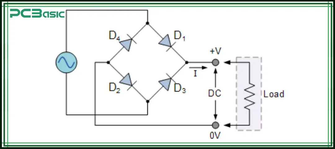
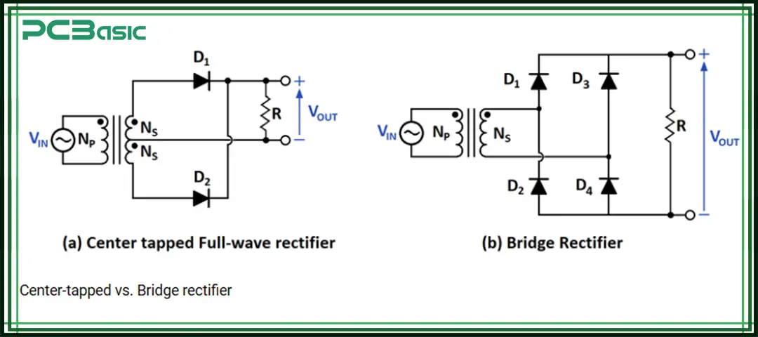
There are mainly two implementation methods for the full wave rectifier circuit:

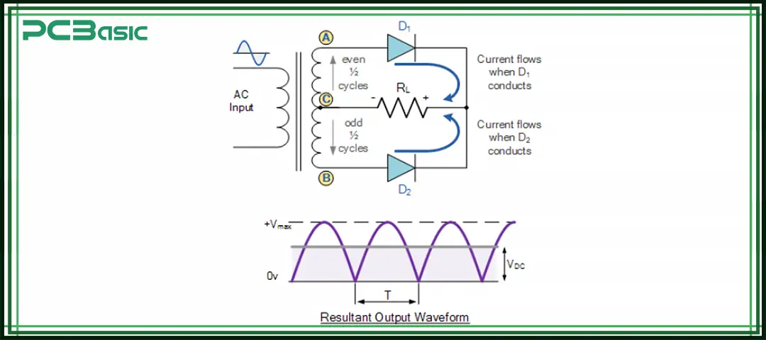
This circuit consists of a centre-tapped transformer, two rectifier diodes and a load resistor. During operation, in the positive half cycle of the AC, diode D1 conducts and D2 is reverse, and the current flows unidirectionally through the load. During the negative half cycle, D2 conducts and D1 is reverse-biased, but the load current still flows in the same direction. In this way, each half cycle has a diode at work, ultimately outputting continuous pulsating direct current (DC).
Its advantages are that it has a simple structure and only requires two diodes. And compared with the half wave rectifier, it has a higher DC voltage and a smoother output. However, a special centre-tapped transformer must be used, which will increase both cost and volume. Moreover, each diode has to withstand a peak inverse voltage (PIV) twice the input voltage. This circuit is an early form of the full wave rectifier circuit.
The bridge rectifier, or full bridge rectifier, is composed of four rectifier diodes in a bridge configuration and does not require a centre-tapped transformer. In the positive half-cycle, diodes D1 and D2 conduct, while D3 and D4 are reverse-biased, and the current flows unidirectionally through the load. During the negative half cycle, D3 and D4 4 conduct, while D1 and D2 are reverse-biased, and the current remains in the same direction.
This structure does not require a centre-tapped transformer, has a higher transformer utilization rate, and is smaller and more compact than the center tap design. However, the drawback is that each half cycle has two diodes conducting simultaneously, resulting in a voltage drop of approximately 1.4V (for silicon diodes). Under high current conditions, it is prone to heat generation and requires the addition of a heat sink. The bridge full wave rectifier is now the most widely used and common rectifier circuit.

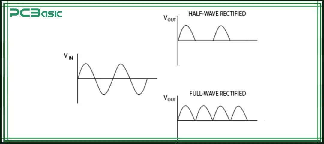
The output of a full-wave rectifier circuit is actually a pulsating DC waveform. Without a filter, the output would be a series of positive pulses. Each half cycle of the AC would be rectified once, so the output frequency would become twice the input frequency. For example, if the input is 50 Hz, the output would be 100 Hz.
Adding a filter, such as connecting a capacitor across the load, can make the waveform smoother, reduce ripple, and obtain an output that is closer to a stable DC voltage. Precisely because of this, the output of full wave rectification is much smoother than that of half wave rectification, so it is very suitable for use in power supply applications.
Here are the important formulas for a full wave rectifier:
• DC Output Voltage:
• RMS Current:
• Form Factor:
• Peak Factor:
• Ripple Factor:
(Much lower than the half wave rectifier, which has 1.21).
• Efficiency:
• Peak Inverse Voltage (PIV):
For centre-tapped rectifier: PIV = 2Vm
For bridge rectifier: PIV = Vm
These formulas help in designing and analyzing a full wave rectifier circuit for real-world applications.

Time is money in your projects – and PCBasic gets it. PCBasic is a PCB assembly company that delivers fast, flawless results every time. Our comprehensive PCB assembly services include expert engineering support at every step, ensuring top quality in every board. As a leading PCB assembly manufacturer, we provide a one-stop solution that streamlines your supply chain. Partner with our advanced PCB prototype factory for quick turnarounds and superior results you can trust.
Compared with the half wave rectifier, the full wave rectifier performs better in many aspects and is therefore more widely used in practical circuits:
• Higher efficiency: The half-wave rectifier only utilizes alternating current (AC) for one half cycle, with an efficiency of approximately only 40%. Full-wave rectifiers can utilize both the positive and negative half-cycles simultaneously, achieving an efficiency of approximately 81% and a higher utilization rate of electrical energy.
• Smoother output: Since the output frequency of full wave rectification is twice that of the input AC, the voltage fluctuation is faster, the ripple is naturally smaller, and the resulting direct current (DC) is more stable.
• Higher average output voltage: The DC output voltage of a full-wave rectifier is approximately 0.637 times the peak AC voltage, while that of a half wave rectifier is only 0.318Vm. A higher voltage means a stronger driving force can be provided for the load.
• Better transformer utilization factor (TUF): Full wave rectifiers can make more full use of the secondary winding power of the transformer, reduce resource waste, and maximize the value of the transformer's volume and cost.
• Smaller filter capacitor required: Since the ripple amplitude is lower and the output voltage is already relatively stable, compared with half wave rectification, only a smaller filter capacitor is needed to further smooth the waveform. This not only saves space and material costs, but also helps to miniaturize circuits.
• Higher reliability: The current flow in the load always remains in the same direction, reducing the potential losses of the device caused by frequent reverse current reversals, thereby enhancing the stability and lifespan of the circuit.
• Wide applications: The full wave rectifier is almost a standard configuration in power circuits and is widely used in situations where AC is converted to DC, such as switching power supplies, battery chargers, adapters for laptops and mobile phones, UPS systems, and various consumer electronic products.
The half-wave rectifier is one of the simplest rectifier circuits. Its working principle is to allow one half-cycle of the alternating current (AC) waveform to pass through while blocking the other half-cycle. Just one PN junction diode, along with a load resistor, and sometimes a transformer for isolation or voltage regulation, can convert sinusoidal alternating current into pulsating DC voltage.
The output current of this kind of circuit is unidirectional, but it is not smooth; instead, it is a series of pulses. Therefore, a filter is usually needed to obtain a more stable direct current. Compared with the full-wave rectifier, its efficiency is much lower because half of the waveform of the alternating current is wasted. But precisely because of its very simple structure, it can often be seen in textbooks, laboratory experiments and some rapid prototyping circuits. It can be said that half-wave rectifiers are the first step to understanding the principle of rectification and further learning the types of rectifiers, especially full-wave rectifiers.

|
Feature |
Half Wave Rectifier |
Full Wave Rectifier |
|
Cycle Utilization |
Only one half of AC |
Both halves of AC |
|
Average DC Output |
0.318 Vm |
0.637 Vm |
|
Efficiency |
40.6% |
81.2% |
|
Ripple Factor |
1.21 (high) |
0.482 (low) |
|
Frequency |
f |
2f |
|
Number of Diodes |
1 |
2 (centre-tap) / 4 (bridge rectifier) |
|
Transformer Requirement |
Not required |
Centre-tap or simple transformer |
|
Cost |
Low |
Higher |
|
Applications |
Low power, AM detection |
Power supplies, industrial electronics |
This table highlights why the full wave rectifier is the preferred choice in most rectifier circuits.
The full wave rectifier is a very fundamental and important part of electronic circuits. It can utilize both the positive and negative half-cycles of alternating current (AC), so compared with the half wave rectifier, it is more efficient, and the output direct current (DC) is more stable with less ripple.
It is necessary for students, engineers and electronics enthusiasts to learn and master the full wave rectifier diagram, formulas and working principle. Because when designing power supplies, battery chargers or other DC systems, full wave rectification can ensure the stable and reliable operation of the circuit.

Assembly Enquiry
Instant Quote
Phone contact

+86-755-27218592
In addition, we've prepared a Help Center. We recommend checking it before reaching out, as your question and its answer may already be clearly explained there.
Wechat Support

In addition, we've prepared a Help Center. We recommend checking it before reaching out, as your question and its answer may already be clearly explained there.
WhatsApp Support

In addition, we've prepared a Help Center. We recommend checking it before reaching out, as your question and its answer may already be clearly explained there.
