Global high-mix volume high-speed PCBA manufacturer
9:00 -18:00, Mon. - Fri. (GMT+8)
9:00 -12:00, Sat. (GMT+8)
(Except Chinese public holidays)
Global high-mix volume high-speed PCBA manufacturer
9:00 -18:00, Mon. - Fri. (GMT+8)
9:00 -12:00, Sat. (GMT+8)
(Except Chinese public holidays)
HomePage > Blog > Knowledge Base > Difference Between Active and Passive Filters
A filter is a fundamental circuit element in electronics that plays a critical role in controlling signal frequency content. When designing high-performance circuit boards, engineers often focus on key technical parameters such as processor selection, signal integrity, and power allocation, but neglect filters. In fact, filters play a crucial role in circuit design. Whether it is adjusting the frequency response in an analog audio system or suppressing interference in a high-speed digital interface, the filter is a core component that ensures the stable operation of the circuit. Among the various types of filters, active filters and passive filters are the two most fundamental categories. Basically, it can be said that understanding the difference between active filters and passive filters is closely related to manufacturing costs, layout complexity and functional flexibility.
Today, let's explore this topic together! In this article, we will systematically introduce what is a filter in electronics, its main classifications and the difference between active and passive filters. Now, let's first understand what filters are in electronics.
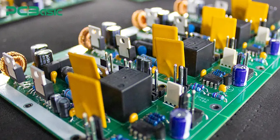
In electronic circuit design, filters are essential circuit blocks used to control the frequency characteristics of signals. The basic principle of a filter is to allow signals of specific frequencies to pass through while suppressing other unwanted frequencies. In this way, the filter can used for signal conditioning, bandwidth limitation, noise suppression, and electromagnetic interference control. This is an indispensable part of analog circuits, mixed-signal systems and high-speed digital circuits.
In PCB design, the typical functions of filters include:
Signal conditioning: that is, ensuring that the next-level circuit only receives the required frequency components.
Noise suppression: that is, shielding power supply noise, common-mode interference, and external electromagnetic interference.
EMI control: helps circuits meet electromagnetic compatibility (EMC) standards.
Frequency shaping: that is, adjusting the signal bandwidth before the analog channel or sampling.
From these functions, we can see that the applications of filters are extensive and crucial. Filters are the core guarantee for the normal operation of electronic products.
There are also many types of filters, and each type can be optimized for specific frequency characteristics or application scenarios. According to the response methods to signals of different frequencies, filters can be subdivided into the following types of filters:
|
Filter Type |
Main Function |
Operating Frequency Range |
Applications |
|
Low-pass Filter |
Allows low-frequency signals to pass while attenuating high-frequency signals |
Below the cutoff frequency |
Audio amplifier output, anti-aliasing filter |
|
High-pass Filter |
Allows high-frequency signals to pass while attenuating low-frequency signals |
Above the cutoff frequency |
High-frequency noise removal, AC coupling circuits |
|
Band-pass Filter |
Passes signals within a specific frequency band while blocking others |
Between two cutoff frequencies |
Band selection in wireless systems, audio equalizers |
|
Band-stop / Notch Filter |
Blocks a specific frequency band while allowing others to pass |
All except the stopband |
Power-line interference rejection (e.g., 50/60Hz), harmonic suppression |
From the perspective of composition principles, filters can mainly be divided into two categories: active filters and passive filters. The different types of filters in the above table are the basic forms of filter design. They are also the reference basis for the subsequent selection of active filters or passive filters. Next, we will introduce the active filters and passive filters respectively, and further compare the differences between the two.
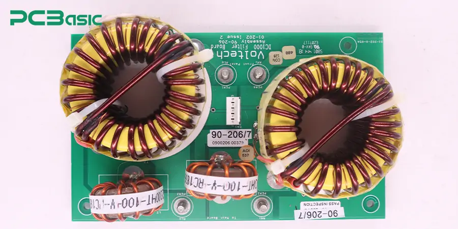
Passive filters are one of the most fundamental and common implementation methods. They are composed of passive components - resistors, capacitors and inductors - and can work without any external power supply. Passive filters are mainly used to remove high-frequency interference in circuits, control signal bandwidth or achieve frequency selectivity. According to the goals of circuit design, they can construct filter circuits with various functions.
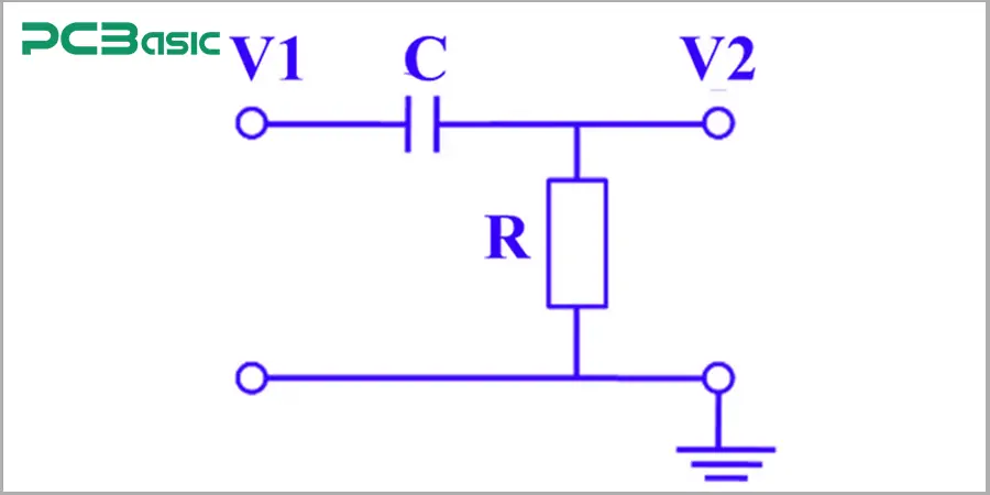
RC low-pass/high-pass filter: Suitable for the basic processing of low-frequency signals;
LC bandpass/band-stop filter: Commonly found in RF and communication systems;
π-type power supply filter: Used for power supply ripple suppression and EMI control.
1. No power supply required: the circuit structure is simple and highly reliable;
2. Low cost: components are readily available and the manufacturing cost is low;
3. Strong high-frequency adaptability: particularly suitable for use in radio frequency (RF) and power supply systems.
1. Unable to provide gain: can only attenuate or pass through signals;
2. Limited design flexibility: the frequency response mainly depends on the physical values of the components and is not easy to be dynamically adjusted.
3. Large inductor volume: in some applications, it may occupy a considerable amount of PCB space.
In actual PCB projects, passive filters are commonly found in EMI suppression at power input ports, termination circuits for high-speed signal traces, and matching networks in RF modules, etc.
An active filter is a filter circuit constructed based on active components (such as operational amplifiers). While filtering the signal, it can also achieve functions such as amplification, impedance isolation and adjustable frequency response.
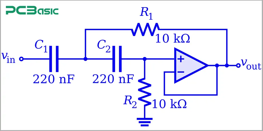
Active filters are usually composed of the following components:
Operational Amplifier (Op-Amp): provides gain and signal processing capabilities;
Resistance, capacitance (R/C): set the frequency response characteristics;
Usually, bulky inductive components are not required. This eliminates the need for bulky inductors, a key difference from many passive filters.
*In electronic circuits, the topological structure refers to the connection mode among various components (such as resistors, capacitors, inductors, and operational amplifiers) in the circuit. It describes "who connects whom", regardless of the specific size, arrangement sequence or position of the components.
Sallen-Key structure: commonly used in low-order low-pass/high-pass filters;
MFB (Multiple Feedback) structure: It can achieve higher quality factor (Q) and precise bandwidth control;
State Variable Filter: It can simultaneously achieve low-pass, high-pass and bandpass outputs, and has strong flexibility.
These are all effective ways to implement different types of filters, depending on the design goals.
1. Amplifying signal: enhance the signal amplitude while filtering;
2. Adjustable frequency response: the cutoff frequency can be dynamically set by adjusting the feedback resistor and capacitor.
3. Good input-output isolation: reduces load coupling interference and enhances system stability;
4. No inductors required: suitable for space-constrained or cost-sensitive application scenarios.
1. Power supply is required: the power supply design needs to take into account the power consumption of the filter circuit and noise isolation.
2. Limited high-frequency performance: constrained by the gain-bandwidth product (GBW) of the operational amplifier;
3. More complex layout: more precise PCB routing and power decoupling design are required.
So, what exactly is the difference between active filters and passive filters?
|
Comparison Aspect |
Active Filters |
Passive Filters |
|
Definition |
Filters that use active components like op-amps in addition to resistors and capacitors. |
Filters that use only passive components such as resistors, capacitors, and inductors. |
|
Power Requirement |
Require external power supply to operate. |
Do not require any external power source. |
|
Components Used |
Use op-amps, resistors, and capacitors (no inductors). |
Use resistors, capacitors, and inductors (no active components). |
|
Size and Weight |
More compact as they avoid bulky inductors. |
May be larger and heavier due to inductors. |
|
Gain |
Can amplify the input signal. |
Cannot amplify; signal can only attenuate. |
|
Frequency Response |
Precise and flexible control over frequency characteristics. |
Limited control, especially at low frequencies. |
|
Cost |
Generally more expensive due to active components. |
Typically cheaper with fewer components. |
|
Typical Applications |
Used in audio processing, communication systems, active tone control. |
Common in RF circuits, power supplies, analog front ends. |
|
Signal Strength Handling |
Not ideal for high-voltage or high-current signals. |
Can handle higher signal levels without distortion. |
|
Noise Performance |
May introduce noise due to active devices. |
Lower intrinsic noise if designed correctly. |
|
Filter Types Supported |
Can implement low-pass, high-pass, band-pass, band-stop, with gain. |
Also support same filter types but only with attenuation. |
|
Flexibility in Design |
Highly configurable using feedback networks and gain control. |
Limited design flexibility. |
|
Classification of Filters |
Part of the active filters group in electronic filter classification. |
Part of the passive filters group in classification. |
This table clearly shows the main differences between active and passive filters, including their differences in component composition, power requirements, volume size and performance. These comparisons not only help to understand their working principles, but also provide a basis for actual selection. In PCB projects, the application of filters is also very extensive.
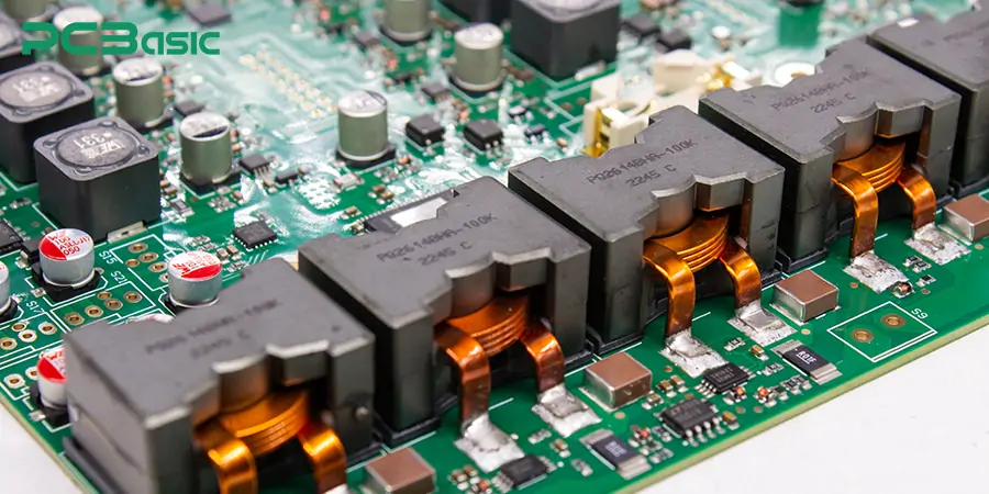
In modern electronic design, filters are an indispensable component in PCB circuits. Whether dealing with analog signals or power management, the rational use of different types of filters can effectively improve the performance and stability of the system. The main applications of filters in PCBs are:
1. Audio and signal processing circuits
In PCB circuits such as audio amplifiers, equalizers, and low-noise amplifiers, active filters are widely used for precisely controlling frequency response and signal amplification. This type of application has high requirements for distortion and bandwidth. While active circuits can provide the required gain and accuracy and are the preferred choice in such circuits.
2. Power filtering and decoupling
In switching power supply modules (SMPS) and linear regulators, passive filters (such as LC and RC filters) are widely used to suppress ripple and high-frequency interference. They do not require external power supply and can handle high voltage and large current. They are common filtering schemes in power PCB design.
3. Communication and radio Frequency circuits
Radio frequency and high-speed communication systems have extremely high requirements for frequency selectivity. Therefore, bandpass filters or band-stop filters are often adopted to achieve signal filtering and frequency band control. According to the performance requirements, designers may choose passive filters with high Q values, or combine active and passive filters in a compact design to enhance the effect.
4. EMI/EMC control
To meet the electromagnetic compatibility (EMC) standards, passive filters are used in PCB design to suppress noise at the input and output ports. For example, common mode chokes, capacitor arrays, etc., can reduce the influence of electromagnetic interference (EMI) on other circuits and are one of the key applications of filters.
5. Simulate the interface between the front end and the sensor
In the sensor signal acquisition system, the analog front end on the PCB usually requires noise suppression and bandwidth limitation. Active filters can be used for signal conditioning, isolation and pre-amplifier to ensure that the signal maintains good quality before entering the ADC.
Filters are so widely used in PCBs. Then, how to choose active or passive filters in PCB design?
In PCB design, active filters are usually suitable for applications that require signal amplification, precise frequency response, and compact size, such as audio circuits, sensor interfaces, etc. Passive filters are suitable for scenarios with high voltage, high current or no need for amplification, such as power filtering and EMI suppression.
In conclusion, when choosing an active or passive filter, it is necessary to make a judgment based on multiple aspects such as power supply conditions, signal strength, size requirements, and cost budget.
At PCBasic, we are well aware of the significance of filters in the design of electronic circuits. We support seamless integration of active filters and passive filters into the PCB layout. Our engineering team can assist you in choosing the most suitable filter solution based on your specific application requirements. From low-pass, high-pass to complex bandpass networks, PCBasic can achieve efficient and precise integrated design and manufacturing of filters.
Choosing PCBasic is not merely about obtaining a PCB; it's about getting a complete and optimized circuit solution.
Whether it is an active filter or a passive filter, they are both key links to ensure the performance and signal integrity of the PCB system. Understanding the difference between active and passive filters is helpful for finding the best balance among cost, functionality and manufacturability. The correct selection of active or passive filters will determine whether your product can achieve stable operation and high-quality delivery. Choose PCBasic to get your customized electronic circuit solution!
 About PCBasic
Time is money in your projects – and PCBasic gets it. PCBasic is a PCB assembly company that delivers fast, flawless results every time. Our comprehensive PCB assembly services include expert engineering support at every step, ensuring top quality in every board. As a leading PCB assembly manufacturer, we provide a one-stop solution that streamlines your supply chain. Partner with our advanced PCB prototype factory for quick turnarounds and superior results you can trust.
Assembly Enquiry
Instant Quote
Phone contact

+86-755-27218592
In addition, we've prepared a Help Center. We recommend checking it before reaching out, as your question and its answer may already be clearly explained there.
Wechat Support

In addition, we've prepared a Help Center. We recommend checking it before reaching out, as your question and its answer may already be clearly explained there.
WhatsApp Support

In addition, we've prepared a Help Center. We recommend checking it before reaching out, as your question and its answer may already be clearly explained there.
