Global high-mix volume high-speed PCBA manufacturer
9:00 -18:00, Mon. - Fri. (GMT+8)
9:00 -12:00, Sat. (GMT+8)
(Except Chinese public holidays)
Global high-mix volume high-speed PCBA manufacturer
9:00 -18:00, Mon. - Fri. (GMT+8)
9:00 -12:00, Sat. (GMT+8)
(Except Chinese public holidays)
HomePage > Blog > Knowledge Base > The Ultimate Guide AC Capacitor Wiring Colors
AC capacitors are used across residential, commercial, and industrial HVAC systems, including power supplies, motor-start, and motor-run applications. In a capacitor the electrical energy can be stored and released when required. This helps the motor to start, the compressor to run efficiently, and the fans to spin properly. To keep the capacitors and components working properly, it is essential to understand the color code of wires, the purpose of each terminal, and the proper installation of the wires. This is done to prevent malfunction or efficiency loss of the equipment.
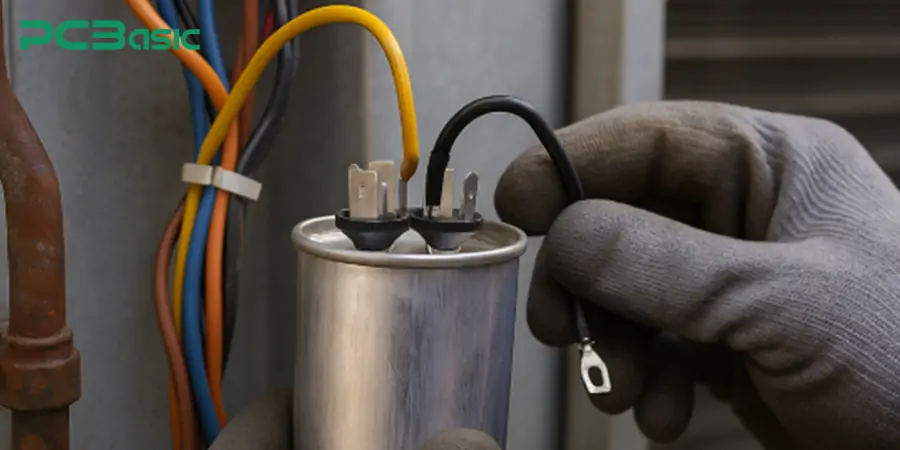
AC capacitors are used in AC (Alternating Current) motor circuits as well as in heating, ventilation, and other air conditioning or HVAC equipment. AC capacitors improve power factor by reducing the phase difference between the voltage and current waveforms. By doing so, it also reduces the reactive power flow. This results in an increase in energy efficiency and a reduced electrical load on the power supply.
The AC capacitor contains plates (usually metal or electrically conductive) that are insulated from each other. The capacitor is a vital component of single-phase motors. It allows a phase difference between the current that flows through the auxiliary winding and the current that circulates in the main winding. If there is no phase difference, then the motor will produce a pulsating magnetic field instead of a rotating field. Hence, the phase difference is required. Furthermore, capacitors allow single-phase motors to run on alternating current.
The following are some of the key operations:
Start Assist: Start capacitor provides a jolt of high voltage when the motor is started. This spike creates a large phase shift between the current in the motor’s primary and start windings. This produces the required torque in order to start the motor.
Run Efficiency: Run capacitors remain in the circuit during the motor operation. These capacitors maintain the voltage and current ratings. This provides a smoother performance and constant RPMs.
Dual Function Design: With certain models, a capacitor has both starting and running functionality in one, and such a capacitor is referred to as a dual capacitor. These are often used for systems in which both the fan and compressor motors need support.
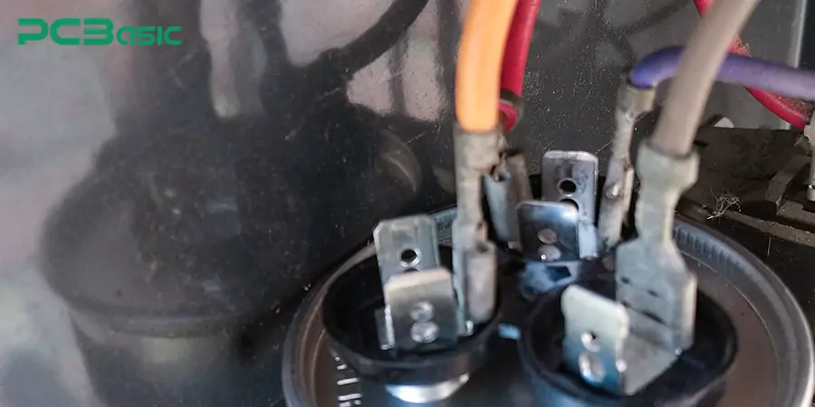
AC capacitors are classified depending on their role in a motor circuit. The three most common types are:
· Start capacitors
· Run capacitors
· Dual capacitors
A temporary phase shift is provided by start capacitor, which gives the motor extra starting torque to start rotating under load. When the motor reaches a certain predetermined speed, the start capacitor is removed from the power circuit. They are usually of a higher physical size, since more energy needs to be stored and released rapidly on motor startup.
Unlike start capacitors, run capacitors stay connected while the motor is running. It stores less electrical charge (low capacitance) than a start capacitor, but it plays a crucial role in running the motor efficiently. These capacitors deliver a steady and moderate amount of capacitance that helps improve the running efficiency and overall performance.
Dual capacitors used in FAN motors and compressors have three terminals (C, FAN, HERM), it combines two capacitors into one package thus simplifying the wiring. They are used in air conditioning and refrigeration applications where both the fan and compressor must be powered simultaneously.
Capacitors are some of the most important components in HVAC systems. They are needed to ensure the indoor blower motor and outdoor compressor unit run smoothly. Capacitors produce the phase shift and provide the energy to start and maintain the running of such motors. Without the presence of capacitors, these systems would struggle to keep up with the airflow and cooling because of higher loads, especially when the voltage fluctuates.
Capacitors for refrigeration devices (such as home refrigerators and other similar appliances, and commercial food freezing refrigerators) utilize compressor motors during startup and running conditions. These motors require an initial surge of power to overcome inertia to begin compressing refrigerant. Capacitors also help with the startup of the compressor, the amount of energy used, and the overall operation of the air conditioner, helping the A/C unit to run more smoothly and experience less wear and tear.
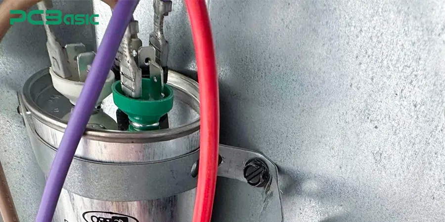
Air conditioners—packaged terminal and room air conditioners, included—depend on capacitors to operate the internal fan motors on both the blower and condenser sides, as well as the hermetically sealed compressor. The capacitor ensures the compressor runs properly and provides the appliance with a long lifespan and also acts as a stabilizer and energy-saving device for the air conditioner. This combination ensures the delivery of cool air and is efficient in its energy use.
For industrial applications, AC capacitors are incorporated in many single-phase motors responsible for driving machinery such as water pumps, air compressors, conveyor systems, and other types of heavy equipment. The capacitors provide a better startup and increased process efficiency of the motor, resulting in lower power losses and contributing to the stabilization of industrial processes.
In automotive applications, capacitors are applied for many different purposes, including in ignition modules, in HVAC blower motors, or in some infotainment or control systems featuring phase-shifted currents or short-term energy storage. In such systems, capacitors are used to deliver steady voltage, faster motor responses, and less electrical noise, and even provide added performance and long life for the electronics and mechanicals in our vehicles.
Standard wire colors make it easier to determine which terminal is which with capacitor terminals.
C (Common)
F (Fan)
H (Hermetic)
S (Start)
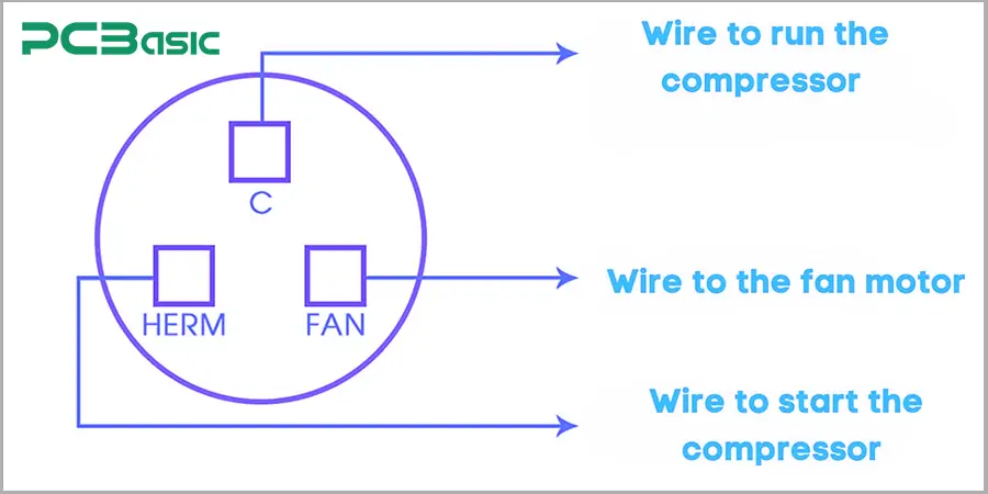
Knowing the wire color codes reduces mistakes in cabling, the risk, and makes service easier than ever. There is a classic color code based on common assignments used in the US and Europe; however, there's no universal standard.
The color codes used in AC capacitor wiring (according to its terminals) are extremely crucial. Below are the popular wire colors and their typical terminal name.
Brown Wire — Fan Terminal (F)
Normally, brown wires are used for the fan motor (blower), and the gray wire is used for the power supply of the air handler. This terminal is typically marked as F or FAN on the capacitor. This brown wire supplies the current and phase shift required for the fan motor to work properly. In some models or certain manufacturing brands, the insulation color of this wire may be orange instead of brown, but brown is the most commonly recognized standard.
Yellow Wire — Terminal H of the Hermetic Compressor
The yellow wire is for the HERM (or Hermetic terminal) of the capacitor which connects to the compressor. In AC capacitor wiring, this wire is responsible for sending power to help perform the initial startup and operation. The terminal it joins is usual said to be H, HERM, or Hermetic. Yellow is commonly used for this connection due to its visibility, and it is consistent with most other HVAC systems, so when the technician is servicing and maintaining all systems, they are easily identified.
Common Wire — Common Terminal (C)
The Common wire connects to the C terminal of the capacitor and serves as the shared return path for both the fan motor and compressor. In AC capacitor wiring, this wire is usually black or blue in most systems. The common terminal (C) serves as the shared electrical return path for both the fan and compressor circuits. It is best that this wire be properly identified and connected, as an improper connection to the common terminal could energize the system to the extent that the system fails or burns out.
Other Colors (Red, Black, Blue) Exception Cases
Some additional colors, such as red, black, and blue, can be used for special connections or non-standard configurations. For example, the red wire is sometimes used to start capacitors or to energize relay overload protectors. Black wires are typically used for the line or hot connection, while neutral is usually white. However, if it is not the common terminal, and in more complex cap configurations, a third wire may also be blue. Since the connection of this wire may not be standardized, the capacitor label must be checked, along with the wiring diagram for the unit, before making any connections.
|
Terminal |
Abbreviation |
Function |
Typical Wire Color |
|
C |
Common |
Shared return path |
Black / Blue |
|
F |
Fan |
Fan motor power |
Brown |
|
H |
Hermetic |
Compressor power |
Yellow |
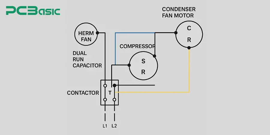
AC capacitor wiring diagrams indicate the type of installation (whether it’s inside or outside the equipment) and show the connections to the capacitor terminals. A dual capacitor is used because it can handle two components (a fan motor and compressor motor) with one housing that has three terminals. These capacitor terminals are designated C, F, and H or HERM.
AC capacitor wiring has its challenges but after learning them, it’s not that bad. Some of the things that need to be done before the AC capacitor wiring are:
Utilities Off: Disconnect the system at the breaker or always disconnect switch.
· Discharge capacitor: Now, connect a 10kΩ, 5-watt (or higher) resistor in series between the capacitor terminals using insulated leads. Let the charge safely bleed off before handling. Avoid direct shorting.
· Check with Meter: Test capacitance in mics for microfarads (µF) against label ratings.
· Consult Terminals: Replace any bent or corroded spade connectors, then make sure the fit is tight.
· For AC capacitor wiring:
Look for Terminals: Review the capacitor labels like Common (C), fan (F), hermetic compressor (H), sometimes start (S), etc.
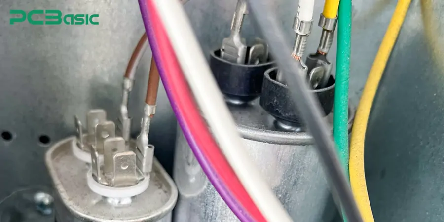
1. Same Colored Wires: Connect each wire to its designated terminal: brown to FAN (F), yellow to HERM (H), black/white to COMMON (C).
2. Good Connections: It refers to the right type of insulated 1/4″ push-on connectors that have been crimped well.
3. Re-check: Check if all the wiring is according to the diagram.
4. Energize and watch: Restore power and observe the capacitor, fan, and compressor.
5. Measure Under Load: Using a clamp meter and a voltmeter, verify that the currents are within the specified ranges.
6. Special Conditions: Multiple Capacitors, Replacement, or HVAC Units
Two capacitors: Packages that contain a different run capacitor for the fan and compressor, each with its own common terminal.
· Replacement: Same µF (run & start) voltage (typically 440VAC on residential) and connection terminals.
· HVAC Systems: The Outdoor unit will have a compressor capacitor, and the Indoor blower may have a separate capacitor.
· Safety Measures of AC Capacitors
Discharging AC capacitors is one of the most important safety procedures while working with them. There is always some leftover energy, and this can be extremely dangerous if anyone happens to touch it. A 10kΩ/5-watt (or higher wattage) resistor connected between the capacitor terminals will safely discharge it. In this way, the stored energy is discharged slowly and safely. It is crucial to have a meter and check the voltage of a capacitor to ensure that it is completely discharged. It is safe to handle the part when the reading is close to zero volts only.
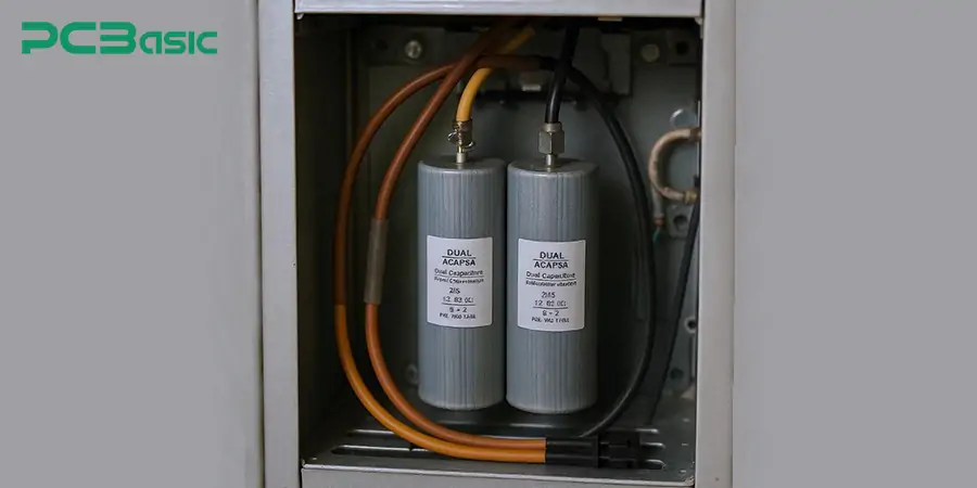
In addition to discharging, several safety measures should be taken whilst working with high voltages. Start by LOTO (lock out, tag out) the power to make sure the system can't be powered up by accident while you're working. Be sure to use insulated tools and protective gear that will provide protection from electricity. Placing the feet on a non-conducting surface, e.g., a rubber mat minimizes the possibility of an electric ground path through the feet and body. It is also recommended to leave both hands free without touching grounded metal, when working with capacitors, so that current won’t pass through the chest. For electrolytics, ensure they are oriented "upwards" to avoid corrosive electrolyte dripping on the PCB.
Another safety measure to consider when working with capacitors is personal protective equipment (PPE). Wear voltage-rated gloves (minimum of 1000 volts) at all times to shield against shock. And wear eye protection — safety goggles or a face shield — again, particularly if an explosion or arc flash (a sudden, violent release of energy caused by a short circuit) is a possibility. The attire should be non-conductive and provide full body coverage, with no metal attachments (rings, necklaces, earrings, etc.) that might act as an accidental conductor. By doing so, it will greatly minimize the risk of danger when working with AC capacitors.
AC capacitors' wiring is extremely crucial because AC capacitors require careful handling. After all, they can hold a high voltage, and high voltage can remain after a device is switched off. Never short the screw terminals directly, it may cause sparks or damage. Insulated and voltage-rated gloves and eye protection shall be used to protect against accidental shock or contact with live circuit conductors or connections.
 About PCBasic
Time is money in your projects – and PCBasic gets it. PCBasic is a PCB assembly company that delivers fast, flawless results every time. Our comprehensive PCB assembly services include expert engineering support at every step, ensuring top quality in every board. As a leading PCB assembly manufacturer, we provide a one-stop solution that streamlines your supply chain. Partner with our advanced PCB prototype factory for quick turnarounds and superior results you can trust.

Assembly Enquiry
Instant Quote
Phone contact

+86-755-27218592
In addition, we've prepared a Help Center. We recommend checking it before reaching out, as your question and its answer may already be clearly explained there.
Wechat Support

In addition, we've prepared a Help Center. We recommend checking it before reaching out, as your question and its answer may already be clearly explained there.
WhatsApp Support

In addition, we've prepared a Help Center. We recommend checking it before reaching out, as your question and its answer may already be clearly explained there.
