Global high-mix volume high-speed PCBA manufacturer
9:00 -18:00, Mon. - Fri. (GMT+8)
9:00 -12:00, Sat. (GMT+8)
(Except Chinese public holidays)
Global high-mix volume high-speed PCBA manufacturer
9:00 -18:00, Mon. - Fri. (GMT+8)
9:00 -12:00, Sat. (GMT+8)
(Except Chinese public holidays)
HomePage > Blog > Knowledge Base > What is a Relay and How Does a Relay Work
A relay is a seemingly simple yet powerful device in the field of electronics. It is an electronic switch that uses electromagnetic principles or solid-state technology to achieve automatic switching and control between circuits. From the timed switching of household appliances to the safety protection of industrial control systems, From the control of high beams in cars to the automated scene switching in smart homes, relays are almost involved in the current control and logic execution of all modern electronic systems.
Relays are the topic we are going to discuss today. This article will provide an in-depth introduction to the definition, functions, structural composition, and several common types of relays. Meanwhile, we will also combine practical application cases to explain the typical uses of relays in household appliances, automotive electronics, industrial equipment and other fields. First of all, let's understand what a relay is.
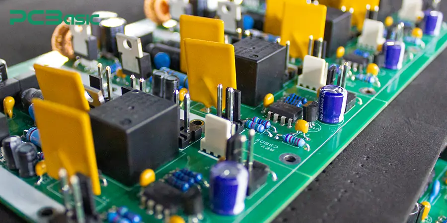
A relay is an electrical relay device, equivalent to a switch controlled by electrical signals. Relays can control high-power load circuits through low-power control circuits and are key components in automation, circuit protection and control systems. The purpose of a relay is to achieve electrical isolation and safety control between circuits. In simple terms, a relay acts as an intermediary, controlling devices such as motors, lights or heaters by receiving signals from a microcontroller or sensor.
There are various types of relays, including electromagnetic relays, solid-state relays, time-delay relays and reed relays, etc. We need to make a choice based on the specific purpose. Common relay structures include 4-pin relays and 5-pin relays. The wiring methods of each relay structure are different and usually need to be illustrated through the relay wiring diagram or the relay schematic diagram.
Whether in control panels, automotive circuits, or industrial automation systems, relays are indispensable core components, providing the system with safe, stable, and programmable power control capabilities. People often compare relays with switches. So, what exactly is the difference between a relay and a switch? There is a brief comparison table below:
|
Item |
Relay |
Switch |
|
Control Mode |
Signal-controlled (automatic) |
Manually operated |
|
Automation |
Supports remote/programmed control |
Local manual only |
|
Isolation |
Yes–isolates control and load circuits |
No isolation |
|
Applications |
Industrial, smart home, automotive, HVAC |
Lamps, power toggles, simple devices |
|
Safety |
Safer–no direct contact with high voltage |
Risk of shock when switching high voltage |
In modern electronic systems, relay devices play a crucial role. It can achieve intelligent control, automatic control and safety isolation of the circuit.
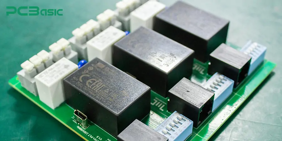
1. Low voltage controls high voltage load
The main purpose of a relay is to control high-power load circuits with low-power signals. For example, microcontrollers can control AC motors, HVAC compressors or lighting systems through relay switches. Electrical isolation between the control end and the load end is achieved through electrical relays, which can thereby enhance the safety and reliability of the system.
2. Achieve automation and logical control
Relays are key to industrial and consumer-grade electronic automation systems. The relay can turn the equipment on or off without human intervention, triggered by sensor signals or logic control signals. Different types of relays can be selected according to the requirements, such as electromagnetic type, solid-state type, delay type, etc.
3. Simplify the circuit design
Relays make the control of complex circuits more concise. A controller can control different loads through multiple relays, forming a clear relay wiring logic structure. With the help of the relay wiring diagram and relay symbol, relays can be conveniently integrated into the circuit schematic diagram.
4. Wide application compatibility
Whether it is a 12V DC fan or a 240V AC water pump, the relay can achieve compatible switching. In common designs, the 4-pin relay wiring diagram or the 5-pin relay wiring diagram is referred to to connect contacts such as normally open (NO), normally closed (NC), and common terminal (COM).
5. Protection and isolation function
Electrical relays are not only used for control, but also have the capabilities of electrical isolation and overload protection. When faults such as overcurrent or short circuits occur, the relay can promptly disconnect the circuit to protect critical equipment. This can ensure the safe operation of the system, which is of great significance, especially in critical control systems.
Before understanding how relays work, let's first take a look at the basic structure and pin diagram of relays. This is helpful for us to better understand the working principle of the relay.
4-pin relay diagram
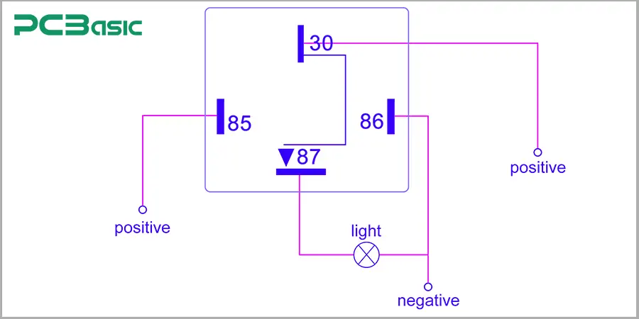
Standard 4-pin relays include:
Pins 85 and 86: Control coil
Pins 30 and 87: Load switch contacts
When the coil is energized, the space between 30 and 87 closes and the current begins to flow. This configuration is suitable for simple on/off control, such as lighting, fans, etc.
5-pin relay diagram
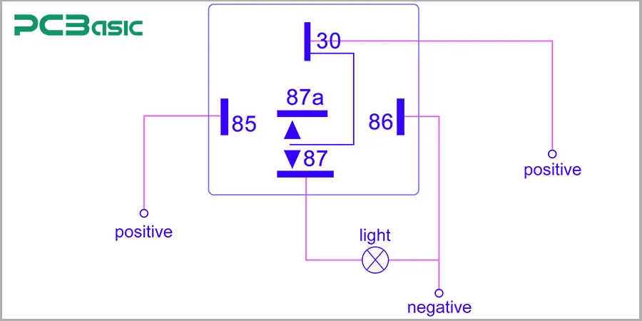
A 5-pin relay has one more normally closed contact than a 4-pin relay:
Pins 85 and 86: Control coil
Pin 30: Public terminal (COM)
Pin 87: Normally open (NO)
Pin 87a: Normally closed (NC)
When the relay is not powered on, 30 is connected to 87a. After powering on, switch to 30 and 87. This structure is suitable for circuit switching, such as immediately connecting another circuit after the power supply is disconnected.
Whether it is a 4-pin relay or a 5-pin relay, their working principles are basically the same, that is, when the coil is energized, it drives the internal contacts to act.
A relay is essentially an electrical control switch. A typical electrical relay contains a coil and a set of movable contacts inside, and these contacts connect or disconnect circuits through magnetic force.
When a voltage is applied across the coil, a magnetic field will be generated inside the relay. This magnetic field attracts a metal armature (also called a moving contact), thereby changing the state of the contact. The specific actions depend on the types of relays. Common ones include:
Normally open (NO) relay: By default, the contacts are open. Only after the coil is energized do the contacts close and the current begins to flow.
Normally closed (NC) relay: By default, the contacts are closed. When powered on, the contacts open. It is used in scenarios where the load needs to be automatically cut off when power is required.
The following is a specific example. Suppose you want to use a 5V microcontroller to control a 220V AC light bulb. The microcontroller sends a low-voltage signal to the coil of the relay, and the internal contacts of the relay switch, thereby allowing a high-voltage current to flow to the bulb. Throughout the entire process, the control terminal and the high-voltage load terminal are isolated, which greatly enhances the safety of the circuit.
This is precisely the fundamental working principle of a relay: by driving the internal contacts to act through the electrical signal at the control terminal, the on-off of the load circuit is achieved. Whether a relay can reliably perform these actions is closely related to the configuration type of its contacts. Next, let's take a detailed look at the types of relay contact configurations.
Contacts are the core part of an electrical relay. It is responsible for cutting off or connecting circuits, thereby controlling the flow of current. The following are several of the most common types of relay contact configurations:
1. SPST - Single Throw (Always Open)
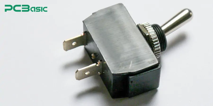
This is the simplest configuration of a relay switch. Including:
One input terminal and one output terminal
By default, it is always Open (Normally Open, NO)
When the relay coil is energized, the contacts close and the current can pass through
This configuration usually appears in the 4-pin relay wiring diagram and is used for basic on/off control, such as controlling lights or fans by a microcontroller.
The relay wiring method is also very simple: Pins 85 and 86 are connected to the coil control terminal, and pins 30 and 87 are connected to the load circuit.
2. SPDT - Single Pole Double Throw
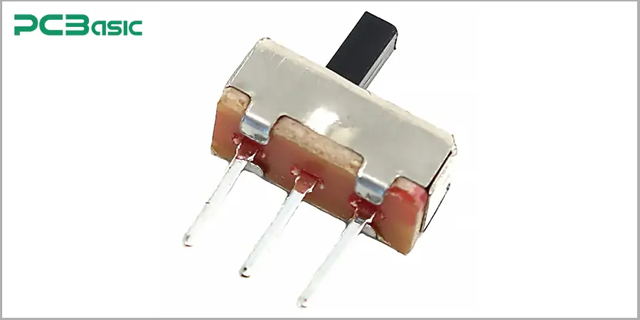
The single-pole double-throw (SPDT) relay has:
A public terminal (COM)
A normally open (NO) contact
A normally closed (NC) contact
This configuration is very common in the 5-pin relay wiring diagram and enables switching between two circuits - one disconnected and the other connected. It is highly suitable for scenarios where the output terminal needs to be switched, such as power switching, motor forward and reverse rotation, etc. This highly flexible structure is a widely adopted solution in automotive electronics and industrial control.
3. DPDT - Double Pole, Double Throw
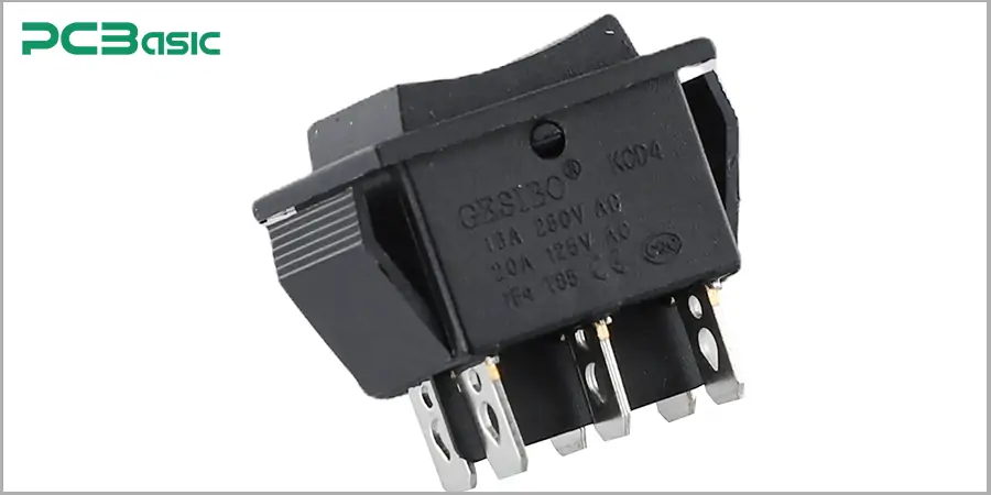
This type of relay has:
Two input terminals (two knives)
Each input is respectively connected to a NO and an NC output (double throw)
Essentially, it is like two SPDT relays integrated into one housing, sharing a set of control coils. It can switch two sets of independent circuits simultaneously.
Although this type of configuration is not common in 4-pin relay diagrams, DPDT is very practical in some complex relay devices, such as scenarios like simultaneously switching multiple power supplies and driving bidirectional motors.
4. Latching Relay
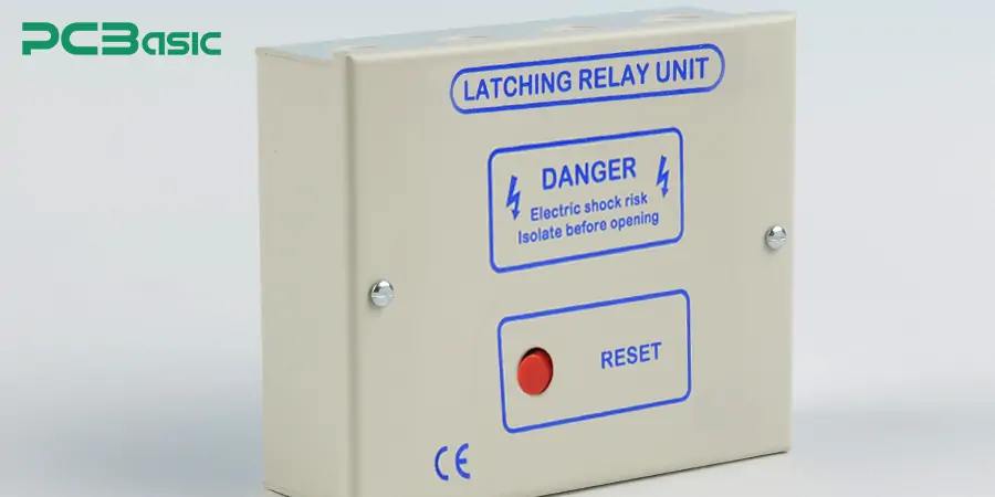
Unlike ordinary relays that automatically reset after power-off, self-locking relays remain in their current state even after power-off. The contact structure of this type of relay can be SPST or SPDT, but its control method utilizes pulse signals rather than continuous current. It is highly suitable for energy-saving systems or application scenarios that need to maintain their status even after power failure, such as smart lighting and memory control systems.
|
Relay Type |
Working Principle |
Key Advantages |
Common Applications |
Wiring Diagram / Structure |
|
Electromechanical Relay (EMR) |
Coil generates magnetic force to move mechanical contacts |
Low cost, intuitive design, easy to wire |
General-purpose switching, household devices, automotive electronics |
4 pin or 5 pin relay wiring (SPST/SPDT) |
|
Solid State Relay (SSR) |
Uses semiconductor components (e.g., TRIAC, MOSFET) for switching |
Silent operation, fast switching, no mechanical wear |
Automation, high-speed switching, vibration environments |
Integrated package, no physical contacts |
|
Reed Relay |
Coil creates magnetic field to close hermetically sealed reed contacts |
Fast response, compact size, sealed structure |
Logic control, signal switching, test instruments |
Miniature form, simple internal design |
|
Latching Relay |
Maintains contact state after coil is de-energized via magnetic or mechanical latching |
Energy-saving, power-off memory retention |
Emergency stop circuits, memory circuits, smart control systems |
May include set and reset coil terminals |
Relays play a crucial role in numerous electronic and electrical systems. Whether it is designing a simple control circuit or developing an industrial automation system, a relay device is a reliable solution for controlling high-power loads with low-power signals.
1. Industrial automation
In industrial settings, relays are widely used to control mechanical equipment, transmission systems, water pumps and safety interlock systems. Integrating the relay switch into the PLC enables automation engineers to achieve complex sequential control and provide good electrical isolation.
2. Automotive electronics
Automotive relays are indispensable in modern vehicles. It controls multiple key components such as the headlights, oil pump, power Windows and air conditioning. Most cars adopt 12V DC systems, and the commonly used structures are 4-pin relays or 5-pin relays.
3. Household appliances and consumer electronics
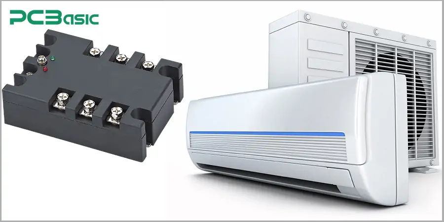
Relay devices are commonly found in washing machines, microwave ovens, air conditioners and smart home controllers. They enable the devices to be automatically turned on or off based on timers, sensors or wireless input. The commonly used types are electromagnetic relays of SPST or SPDT.
4. Power Management and Energy Systems
In power grids, solar energy or battery energy storage systems, relays are used for load switching, fault isolation and backup power control. They are crucial for ensuring operational safety and optimizing energy usage. When the battery voltage is too high, the relay automatically disconnects the load protection system.
5. Telecommunication and signal switching
In telecommunication circuits and test equipment, reed relays or solid-state relays can achieve low-voltage signal path control without mechanical wear. It is often used for the automatic switching of network test systems or audio signal lines.
Although relays are small, they are the control core in electronic systems. Understanding the definition of a relay, the working principle of a relay, and the correct relay wiring method is of crucial importance for both electronic engineers and enthusiasts. Whether you are using relay switches for automation control or studying relay diagrams for vehicle modification, this basic knowledge will open the door to electrical control for you.
Time is money in your projects – and PCBasic gets it. PCBasic is a PCB assembly company that delivers fast, flawless results every time. Our comprehensive PCB assembly services include expert engineering support at every step, ensuring top quality in every board. As a leading PCB assembly manufacturer, we provide a one-stop solution that streamlines your supply chain. Partner with our advanced PCB prototype factory for quick turnarounds and superior results you can trust.
 About PCBasic

Assembly Enquiry
Instant Quote
Phone contact

+86-755-27218592
In addition, we've prepared a Help Center. We recommend checking it before reaching out, as your question and its answer may already be clearly explained there.
Wechat Support

In addition, we've prepared a Help Center. We recommend checking it before reaching out, as your question and its answer may already be clearly explained there.
WhatsApp Support

In addition, we've prepared a Help Center. We recommend checking it before reaching out, as your question and its answer may already be clearly explained there.
