Global high-mix volume high-speed PCBA manufacturer
9:00 -18:00, Mon. - Fri. (GMT+8)
9:00 -12:00, Sat. (GMT+8)
(Except Chinese public holidays)
Global high-mix volume high-speed PCBA manufacturer
9:00 -18:00, Mon. - Fri. (GMT+8)
9:00 -12:00, Sat. (GMT+8)
(Except Chinese public holidays)
HomePage > Blog > Knowledge Base > Diode Polarity: Understanding and Identifying Diode Direction in Circuits
Diode polarity is one of the most fundamental pieces of knowledge about components and is also a key factor affecting whether a circuit can work normally. As a unidirectional conducting semiconductor device, the installation direction of a diode in a circuit - that is, the diode direction - must strictly follow the design requirements; otherwise, it may lead to the failure of circuit functions, and at worst, it may cause component burnout, damage to the entire machine, and even pose safety hazards. Accurately identifying the positions of the diode anode and the diode cathode is a fundamental skill for ensuring circuit performance and product reliability.
This article will systematically explain the knowledge related to diode polarity for you, starting from the basic working principle of diodes, and analyze the meaning of polarity symbols and detail how to quickly identify the direction of devices through diode marking. At the same time, this article also combines the structural characteristics of different types of devices to help you accurately determine the diode positive and negative. Furthermore, we will also explore the practical application specifications of diode polarity in PCB assembly, and separately introduce the special identification methods of LED polarity, helping you avoid faults or damages caused by incorrect diode orientation in the design, production and maintenance stages.
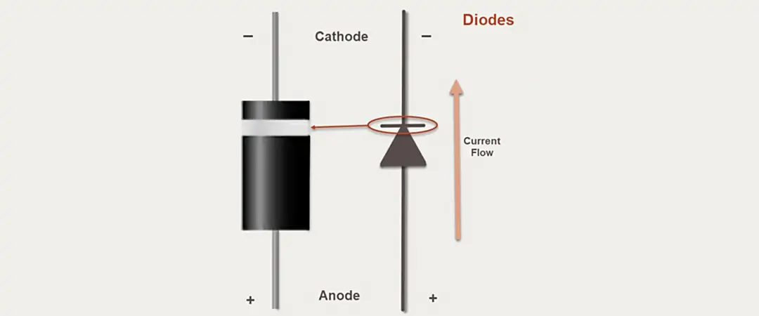
A diode is an electronic device made of semiconductor materials, featuring unidirectional conductivity. That is, it can conduct current in one direction but almost block it in the opposite direction. It plays a significant role in circuits such as rectification, voltage protection, signal modulation, and switch control.
The diode polarity refers to the installation orientation of the two leads of a diode, with one being the anode (positive) and the other the cathode (negative). The diode direction directly determines the way current flows within the device and also decides whether the circuit can operate normally as designed.
In simple terms:
• Diode anode: Positive terminal; internally connected to the P-type semiconductor region; it is the entry point for current into the diode.
• Diode cathode: Negative terminal; internally connected to the N-type semiconductor region; it is the exit point for current from the diode.
The unidirectional conductivity characteristic of a diode only allows current to flow in one diode direction - that is, under the forward bias, while blocking current from passing in the opposite diode direction - that is, under the reverse bias.
• Forward Bias: When the diode anode is connected to the positive terminal of the power supply and the diode cathode is connected to the negative terminal, the PN junction barrier is weakened, allowing current to pass through the diode smoothly. In this state, the diode plays a conducting role.
• Reverse Bias: When the diode cathode is connected to the positive terminal of the power supply and the diode anode is connected to the negative terminal, the PN junction barrier increases, and almost all current is blocked, with only a very small leakage current flowing through. In this state, the diode is in the cut-off state.
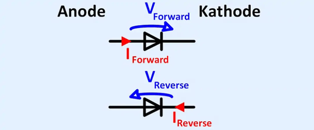
The relationship between the diode anode and the cathode is crucial in the circuit. When forward-bias, electrons flow from the cathode to the diode anode, while according to the traditional definition of current direction, the current flows from the anode to the cathode. This principle of switching between conduction and cut-off makes diodes indispensable components in circuits such as rectification, protection, and signal control.
In the design and reading of electronic circuits, polarity symbols are very important for identifying the diode anode and cathode. Correct understanding and use of these symbols can prevent assembly errors and ensure that the diode operates normally in the circuit as designed.
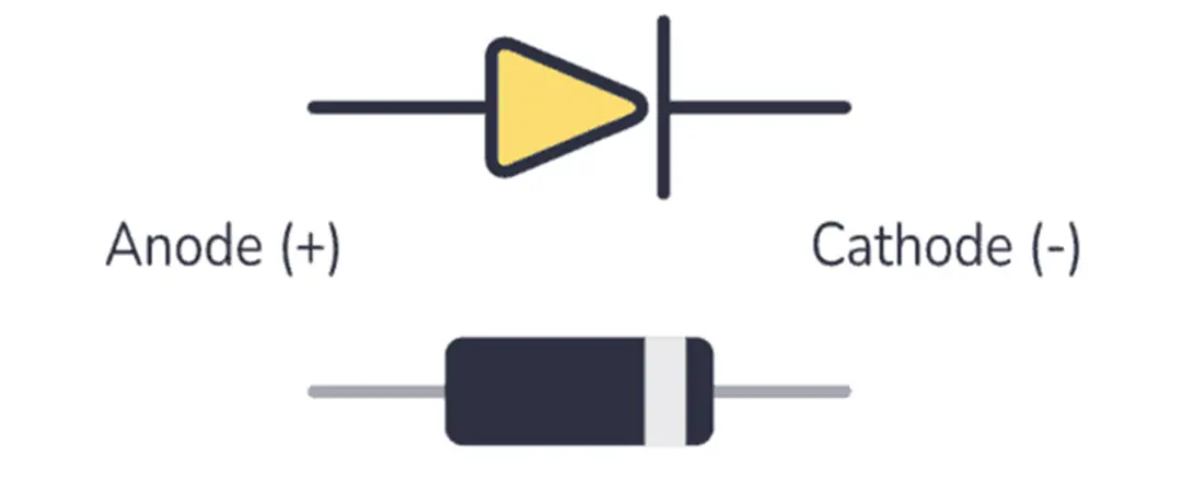
In a circuit schematic diagram, the standard diode symbol consists of a triangle pointing toward a vertical line:
The end of the triangle represents the diode anode, which is the entry point of the current.
The vertical line indicates the diode cathode, which is the exit point of the current.
This symbol vividly represents the diode direction: the current can only flow in the direction from the triangle to the vertical line, and is blocked in the opposite direction.
On actual diode components, manufacturers use some diode markings to help identify the diode cathode side. A common practice is to print a clear colored band on the cathode end of the diode, which is usually white, silver or black, while the unmarked end is the diode anode.
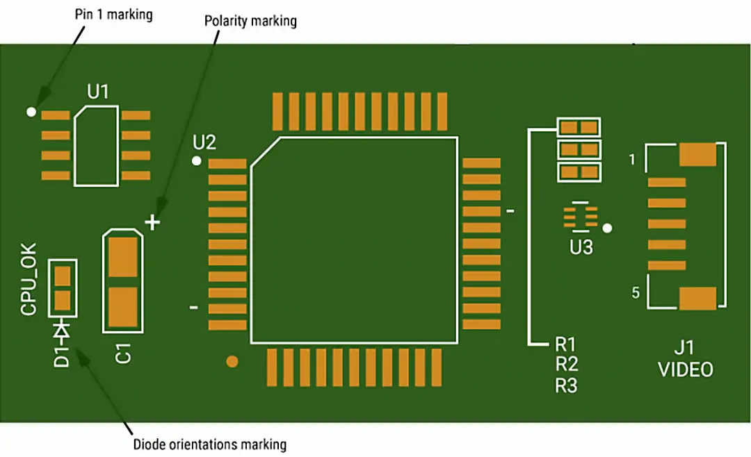
On the PCB, there are usually diode direction markings to indicate to the assembly personnel the correct direction of the components. A short, thick line drawn on the PCB silkscreen corresponds to the cathode side of the diode, facilitating quick positioning during assembly or maintenance. In some designs, a small dot or "+" symbol is used as an additional marking on the anode side of the diode.
This multi-level marking method, from the schematic diagram to the physical component and then to the PCB silkscreen printing, can effectively reduce the risk of assembly errors, especially in mass production. Correctly identifying the diode polarity is an important link to ensure the product qualification rate and reliability.

Time is money in your projects – and PCBasic gets it. PCBasic is a PCB assembly company that delivers fast, flawless results every time. Our comprehensive PCB assembly services include expert engineering support at every step, ensuring top quality in every board. As a leading PCB assembly manufacturer, we provide a one-stop solution that streamlines your supply chain. Partner with our advanced PCB prototype factory for quick turnarounds and superior results you can trust.
In practical applications, diodes of different packaging forms and types have different diode marking methods. Correctly identifying the diode direction is a prerequisite for ensuring the normal operation of the circuit. The following section introduces several common types and their identification methods.
Rectifier diodes (such as the 1N400x series) are often used in power supply circuits. On the black casing, the end marked with a white or silver band is the cathode (negative), and the other end without marking is the anode (positive).
A simple way to judge is that when you see the white ring, it is the negative, and the other side is positive.
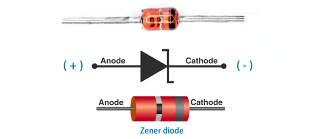
Zener diodes are used to stabilize voltage regulation and prevent overvoltage. The identification methods for different packages are not the same:
• Metal package: The positive terminal is on the flat side and the negative terminal is on the semicircular side.
• Plastic package: The end with the colored band is the cathode (negative ), and the other end is the anode (positive).
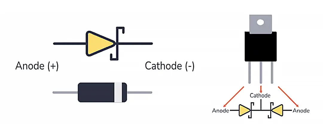
The conduction voltage of Schottky diodes drops rapidly. Many casings are printed with triangular arrow symbols. The end pointed to by the arrow is the anode (positive), and the side of the vertical line is the cathode (negative).
Or in some Schottky diodes, the end with a colored dot (white or red) is the anode and the other end is the cathode.
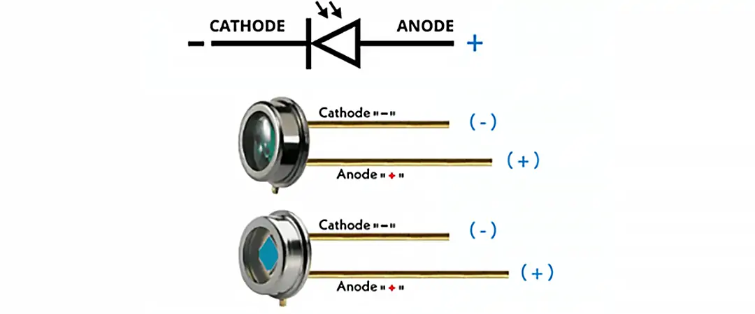
Photodiodes can receive light and generate current.
Metal package: The pin closest to the bump on the base is the positive pole, and the other pin is the negative pole.
Color dot: The pin with the color dot is the positive pole.
Lead length: The longer lead is positive, and the shorter lead is negative.
Rectangular package: The first light-receiving surface is usually marked as the positive pole, and the other side is the negative pole.
|
Diode Type |
Common Package / Appearance |
Cathode (Negative) Identification |
Anode (Positive) Identification |
Remarks |
|
Rectifier Diode |
Black plastic tubular package |
End marked with white/silver ring |
Unmarked end |
Common models: 1N400x series |
|
Zener Diode |
Metal package / Plastic package |
Metal package: semicircular end; Plastic package: colored ring marking |
Metal package: flat end; Plastic package: unmarked end |
Zener diodes are often connected in reverse in circuits |
|
Schottky Diode |
Metal cap or black plastic tubular package |
End with stripe or “K” symbol / End with color dot (point-contact type) |
Unmarked end / End without a color dot |
Low forward voltage drop, high-speed switching |
|
Photodiode |
Metal package / Plastic package / Rectangular package |
Metal package: pin without bump; Plastic package: short lead or end without color marking |
Metal package: pin with bump; Plastic package: long lead or end with color marking |
A rectangular package often marks the light-receiving surface corresponding to the anode |
Quick Identification Tips:
LED (Light Emitting Diode) is a special diode component that emits light when conducting in the forward direction. In the circuit schematic diagram, the polarity symbol of an LED is based on the symbol of a common diode, with two small arrows pointing outward added to indicate the direction of light emission. This symbol not only indicates that the device is a diode, but also clearly demonstrates its light-emitting characteristics.
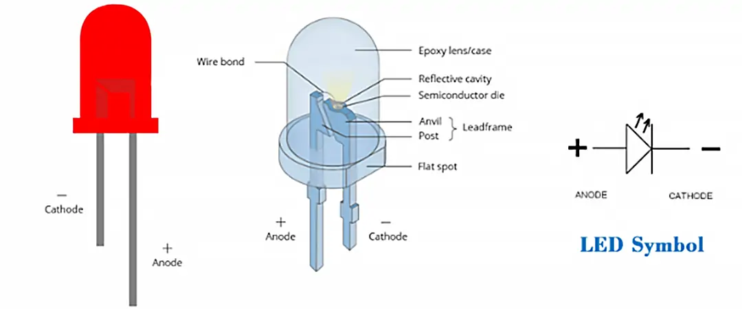
Its polarity determination principle is the same as that of other diodes, still following the direction rule of diode anode vs cathode.
• Diode anode (positive): Usually a longer lead, with no flat edge on the side of the casing.
• Diode cathode (negative): Usually a shorter lead, and the plastic edge of the casing has a distinct flat edge to indicate the direction of the cathode.
Inside the transparent or semi-transparent casing of the LED, the polarity can also be determined with the assistance of a metal support structure:
• The anode is connected to a smaller metal piece to support the light-emitting chip.
• The cathode is connected to a larger metal piece to facilitate heat dissipation and serves as the connection point for the negative.
If the diode polarity of an LED is reversed (the anode is connected to the negative and the cathode to the positive), the LED will not emit light. However, in most cases, this will not immediately damage the device, unless the applied reverse voltage exceeds the rated reverse breakdown voltage of the LED, which may cause chip damage.
In the PCB manufacturing process, ensuring the correct polarity of diodes is a crucial step to guarantee the normal operation of the product. Due to the unidirectional conductivity of diodes, if the diode anode and cathode are connected in reverse during assembly, it will not only cause the circuit to fail to work as designed, but also may lead to overheating and damage of the components, and even result in the scrapping of the entire board.
To avoid such problems, the following are the best practices for diode polarity in PCB assembly:
• Silkscreen alignment check: Before soldering, carefully check whether the diode marking is consistent with the silkscreen direction on the PCB to ensure that the components are placed correctly.
• Visual polarity inspection: During manual assembly or sampling inspection, the direction can be confirmed by observing the diode’s external markings (such as ring markings, lead lengths, flat edges of the package, etc.) to prevent reverse connection.
• Automated equipment verification: When using automated assembly equipment such as pick-and-place machines, it is essential to ensure that the machines can accurately identify and read the diode orientation markings. If necessary, a polarity detection step can be added in the programming to reduce the assembly error rate.
By strictly implementing the above measures, the rework and scrapping caused by incorrect diode polarity can be effectively reduced, and the reliability and yield rate of PCB manufacturing can be improved.
Mastering the diodes' polarity is a fundamental skill for all professionals in the electronics industry. Whether it is identifying the diode anode and cathode or checking the diode marking and understanding the polarity symbol, only when the direction is correct can the circuit work normally and avoid unnecessary losses.
In actual operation, whether it is soldering the diode to the correct position on the PCB, determining the positive and negative leads of the diode, or checking the direction marking of the diode on the schematic diagram, an additional step of confirmation is required to ensure there are no errors.
Truly mastering the polarity of diodes not only enables you to detect and solve faults more quickly but also allows you to be more efficient and confident in circuit design and assembly.

Assembly Enquiry
Instant Quote
Phone contact

+86-755-27218592
In addition, we've prepared a Help Center. We recommend checking it before reaching out, as your question and its answer may already be clearly explained there.
Wechat Support

In addition, we've prepared a Help Center. We recommend checking it before reaching out, as your question and its answer may already be clearly explained there.
WhatsApp Support

In addition, we've prepared a Help Center. We recommend checking it before reaching out, as your question and its answer may already be clearly explained there.
