Global high-mix volume high-speed PCBA manufacturer
9:00 -18:00, Mon. - Fri. (GMT+8)
9:00 -12:00, Sat. (GMT+8)
(Except Chinese public holidays)
Global high-mix volume high-speed PCBA manufacturer
9:00 -18:00, Mon. - Fri. (GMT+8)
9:00 -12:00, Sat. (GMT+8)
(Except Chinese public holidays)
HomePage > Blog > > LED Symbol Explained: Meaning, Variations, and Polarity
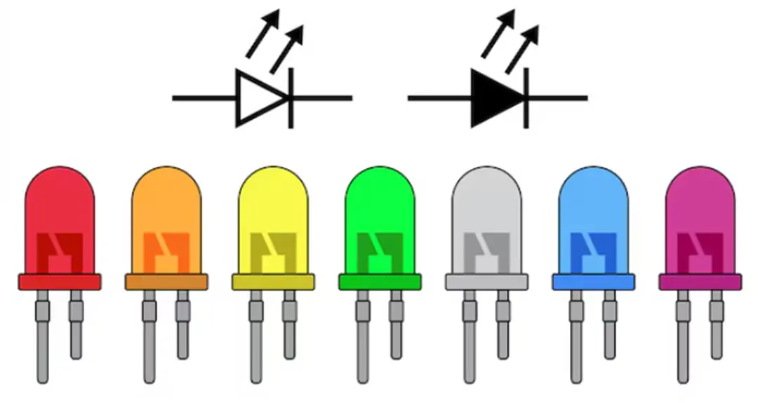
In the field of electronics, each component has a dedicated graphic representation in the circuit diagram. Through these symbols, we can quickly understand the structure and working principle of the circuit. Among them, the light-emitting diode (LED) symbol is one of the more common and easily recognizable symbols. An LED symbol not only indicates the existence of an LED component in the circuit, but also simultaneously informs us of its polarity, working direction, and the specific role it plays in the circuit.
This blog will take you through a systematic understanding of the structure of LED symbols, common different drawing methods, their applications in circuit diagrams, and some historical backgrounds in the development of LED diodes. Meanwhile, this article will also introduce how to quickly identify the LED anode and cathode, why there are different LED colors, and several common types of LEDs in current electronic products. All in all, after reading this article, you will have a comprehensive and in-depth understanding of light-emitting diodes (LEDs).

LED, the full name of which is Light Emitting Diode, is a very important semiconductor device in electronics. Just like the characteristics of ordinary diodes, current can only pass through in one direction and will be blocked in the opposite direction. However, LEDs can not only control the direction of the current when they are forward biased, but also emit light directly.
The light emitted by an LED is not single but determined by the LED chip inside it. The semiconductor material used in the chip and the size of its energy band gap determine the wavelength and color of the light, which is the different LED colors we commonly see.
Due to its low power consumption, long lifespan and fast response time, LED has been widely applied in various fields: from power indicator lights on electronic devices to automotive headlights, traffic signals, advertising displays, and even high-power lighting systems in households and industries. In special fields such as infrared communication and optical sensing, LED diodes also play an irreplaceable role.
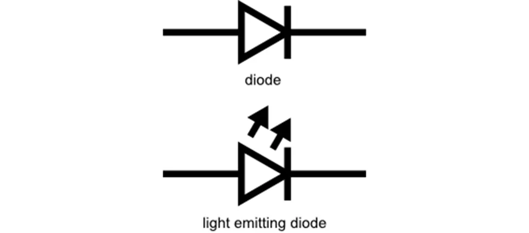
The LED symbol is an improved version of the regular diode symbol. Its structure consists of several parts:
• A triangle points to a straight line: This part is the same as that of a common diode, indicating that the current can only flow from the anode to the cathode, which reflects the unidirectional conduction characteristic of the diode.
• Two small arrows pointing outward: This is the key difference from ordinary diodes. The arrows indicate that the LED can emit light, symbolizing that photons are released from the LED chip.
This simple and intuitive LED symbol not only informs people of its electrical characteristics but also clearly indicates its light-emitting function.

As we mentioned earlier, although the LED symbol is represented based on the standard diode symbol, there is a key difference between them: the LED symbol has an outward arrow, which indicates that it can emit light.
Let's use a table to make a detailed comparison between the LED symbol and the common diode symbol:
Diode Symbol vs LED Symbol Comparison:
|
Feature |
Diode Symbol |
LED Symbol |
|
Basic Shape |
Triangle + line |
Triangle + line |
|
Current Direction |
From anode to cathode |
From anode to cathode |
|
Arrows |
No arrows |
Two outward arrows |
|
Additional Meaning |
Indicates unidirectional conductivity only |
Indicates unidirectional conductivity + ability to emit light |
|
Application in Circuit Diagrams |
Used in rectifiers, switches, and protection circuits |
Used in indicators, lighting, displays, and communication systems |
In electronic design, LED circuit symbols may be different depending on the type and function of LEDs, which are used to help us quickly distinguish diodes of different uses in circuits. In common LED diagrams, there are mainly the following types of symbols:

This is the most common LED symbol, consisting of a triangle, a straight line and two outward arrows. This symbol is usually used in ordinary LED indicator lights, indicating that it can emit light within the visible light range, that is, the small red, green or blue lights we see in our daily lives.

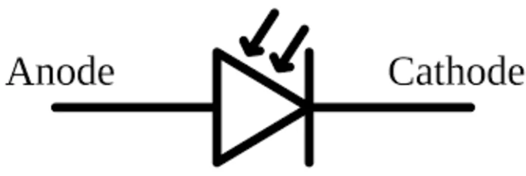
The photodiode symbol looks very similar to that for an LED, but the direction of the arrows is different. The arrow on the photodiode points inward, indicating that it is a device that receives light signals.

The infrared LED symbol is basically the same as that for a standard light-emitting diode symbol, but to distinguish them from ordinary LEDs, "IR" is usually marked on the drawings. It represents that the infrared LED emits the infrared light spectrum that is invisible to the naked eye.

For RGB LEDs, the symbol is more complex. Usually, three arrows are drawn in the RGB LED circuit diagram, or colors are marked beside the symbol to indicate that the LED chip simultaneously contains red, green, and blue LED colors. By adjusting the current size, different colors can be mixed to produce various light effects.
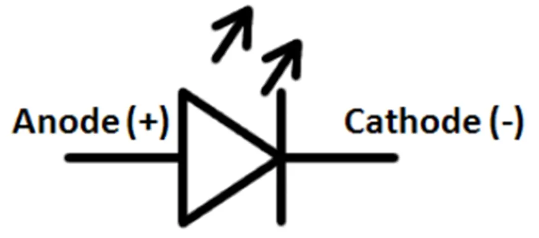
In electronic components, LED polarity is a very important concept. It refers to the fact that LEDs must be connected in the specified direction in a circuit to function properly. The LED is a type of diode, and the working principle of all diodes is the same - they only allow current to flow in one direction. For an LED, the current must flow from the anode (positive) to the cathode (negative) in order to emit light.
In more straightforward terms:
• LED anode = LED positive side, which needs to be connected to the positive terminal (+) of the power supply.
• LED cathode = LED negative side, which needs to be connected to the ground (GND) of the circuit or the negative terminal of the power supply.
If the LED connection direction is incorrect, that is, the LED polarity is reversed, the current will be blocked. Under low voltage conditions, the LED will not light up and will not have any response. However, under high-voltage conditions, if the reverse voltage exceeds the withstand voltage value of the LED, it may cause the LED chip to be damaged permanently.
Therefore, in actual electronic design and assembly, we need to confirm the positions of the LED cathode and anode first, which is the first step to ensure the correct LED connection. If this step is ignored, it will not only cause the LED to not light up, but also may lead to device damage or circuit failure.

Time is money in your projects – and PCBasic gets it. PCBasic is a PCB assembly company that delivers fast, flawless results every time. Our comprehensive PCB assembly services include expert engineering support at every step, ensuring top quality in every board. As a leading PCB assembly manufacturer, we provide a one-stop solution that streamlines your supply chain. Partner with our advanced PCB prototype factory for quick turnarounds and superior results you can trust.
The history of LED diodes can be traced back to the early 20th century. At that time, when scientists were studying semiconductor materials, they discovered that when current passed through certain substances, they would produce a faint light. This phenomenon laid the foundation for the later birth of the light-emitting diode.
The real breakthrough occurred in 1962. American scientist Nick Holonyak Jr. created the first LED diode capable of emitting visible light. It emits red light, and thus he is also known as the "father of modern LED".
The earliest LED colors were only red and had low brightness, and could only be used as simple indicator lights. With the continuous advancement of material technology, researchers have improved LED chips, expanding the LED light spectrum to green, blue, white, and even infrared. Especially the invention of blue LEDs made white LEDs possible, thus completely transforming the field of lighting.
Today, from household light bulbs, automotive headlights, to TV screens and communication devices, devices represented by LED symbols can be seen everywhere. It can be said that from the early experimental discoveries to the current global popularization, LED diodes have become indispensable components in modern electronics and lighting.
The LED symbol is not merely a simple graphic; it represents one of the most important components in modern electronics. Understanding the light-emitting diode symbol, mastering the LED polarity, and understanding the structure of the LED schematic can help us design circuits more accurately, read circuit diagrams and troubleshoot problems.
In simple terms, the LED symbol is a common language that connects engineers around the world. It enables everyone to develop more advanced electronic products based on LED chips, different LED colors, and various LED technologies, promoting continuous technological progress.

Assembly Enquiry
Instant Quote
Phone contact

+86-755-27218592
In addition, we've prepared a Help Center. We recommend checking it before reaching out, as your question and its answer may already be clearly explained there.
Wechat Support

In addition, we've prepared a Help Center. We recommend checking it before reaching out, as your question and its answer may already be clearly explained there.
WhatsApp Support

In addition, we've prepared a Help Center. We recommend checking it before reaching out, as your question and its answer may already be clearly explained there.
