Global high-mix volume high-speed PCBA manufacturer
9:00 -18:00, Mon. - Fri. (GMT+8)
9:00 -12:00, Sat. (GMT+8)
(Except Chinese public holidays)
Global high-mix volume high-speed PCBA manufacturer
9:00 -18:00, Mon. - Fri. (GMT+8)
9:00 -12:00, Sat. (GMT+8)
(Except Chinese public holidays)
HomePage > Blog > Knowledge Base > Capacitor Codes Explained: Types, How to Read, and Applications
Capacitors are one of the key components in modern electronic devices for storing and releasing electrical energy. They can filter signals, smooth out voltage fluctuations, and maintain precise timing functions in circuits. The reliability of devices, whether it's power supplies, smartphones, or automotive electronics, all rely on the role of capacitors.
However, identifying capacitors is not always easy. Many capacitors, such as ceramic capacitors and SMD capacitors, are very small in size. It is almost impossible to print their capacitance, accuracy (tolerance), rated voltage, and other parameters completely on the surface of the device. Moreover, if the capacitor markings are misread or the wrong components are installed, it may cause circuit faults, signal distortion, and even device damage. Therefore, it is very important to quickly identify the capacitance value, tolerance, maximum working voltage, and polarity through short digital, letter combinations, or color band coding.
In this comprehensive guide, we will introduce the relevant content of capacitor codes for you, including the most important how to read capacitors. Next, let's first understand what capacitor code is!
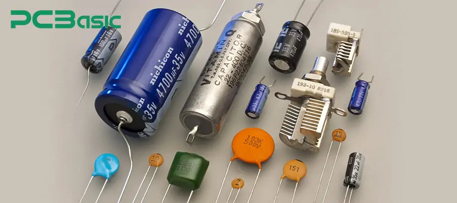
The capacitor code is a shorthand encoding used to represent the key parameters of a capacitor. There are many types of capacitors, such as SMD capacitors and small ceramic capacitors, whose volume is very small and cannot have complete numerical values printed on their surfaces. Therefore, manufacturers use capacitor markings consisting of numbers or letters to present these codes, thereby indicating information such as capacitance, tolerance, etc.
These codes usually include the capacitance value of the capacitor (pF, nF or μF), tolerance (the range within which the actual value may deviate), and sometimes the rated voltage or temperature characteristics. For example: Identifier 104K represents 100,000 pF (i.e. 0.1 μF), with a tolerance of ±10%. Standardized capacitor codes can accurately convey their specifications in a limited space, even for very small components. This is very useful for capacitor identification, SMD assembly, etc.
Understanding capacitor codes is of great importance for those engaged in electronic design, assembly, or maintenance. Because if the capacitor is read incorrectly or the wrong components are used, it may lead to a decline in circuit performance or even complete failure.
Incorrect capacitor values in timing circuits may cause premature or delayed triggering; choosing the wrong power filter capacitor may introduce ripple or noise. Therefore, correct capacitor selection is very important. And correct selection cannot be achieved without the role of capacitor codes.
Understanding capacitor codes and markings can also help speed up fault diagnosis and maintenance. When a device has a problem, we can quickly determine the specifications by observing the capacitor markings without having to remove the components for measurement. It can also reduce assembly errors, ensure the correct placement of components, and shorten production time.
In summary, mastering capacitor codes not only avoids costly mistakes but also improves reliability and speeds up design verification.
The representation of capacitor codes is diverse. This is not only dependent on the type and size of the capacitor, but also on its manufacturing standards. Understanding capacitor codes is helpful for correct selection and can prevent circuit failures. Below, we will introduce several common capacitor codes and the methods for interpreting them for you.
1. Numeric and Alphanumeric Codes
Small capacitors, especially ceramic capacitors and film capacitors, usually use three-digit codes to represent their capacitance values. At this time, the first two digits = the significant digits, and the third digit = the multiplier (representing the number of added zeros, with the unit being pF).
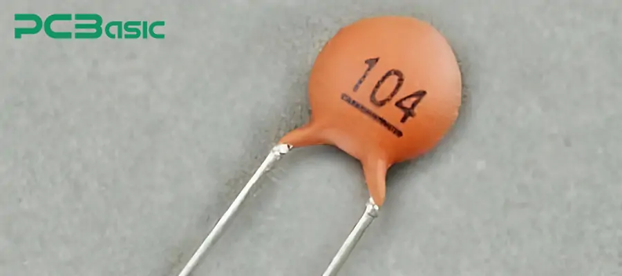
For example:
104→ 10 × 10⁴ pF = 100,000 pF = 0.1 μF
223 → 22 × 10³ pF = 22,000 pF = 0.022 μF
If letters are added to the code, it will form alphanumeric codes. Usually, the letters represent the tolerance of the capacitor: J = ±5%, K = ±10%, M = ±20%
For example:
473K → 47 × 10³ pF = 47,000 pF = 0.047 μF,Tolerance: ±10%
This encoding method is widely used in ceramic capacitor codes and film capacitor codes, and it is the most common encoding form in daily circuit design and maintenance.
2. Capacitor Color Codes
Some older types of capacitors, such as ceramic disc capacitors, use a color-coded system similar to that of resistors to indicate parameters. In this case, the first color band represents the first digit, the second color band represents the second digit, the third color band represents the multiplier, and the fourth color band (optional) represents the tolerance.
For example:
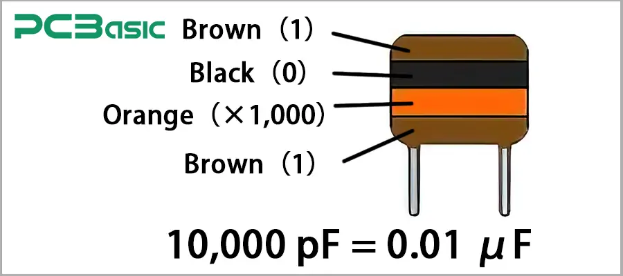
Brown(1)、Black(0)、Orange(×1,000) → 10,000 pF = 0.01 μF
Color code chart:
|
Color |
Digit |
Multiplier |
Tolerance |
|
Black |
0 |
×1 |
|
|
Brown |
1 |
×10 |
±1% |
|
Red |
2 |
×100 |
±2% |
|
Orange |
3 |
×1,000 |
|
|
Yellow |
4 |
×10,000 |
|
|
Green |
5 |
×100,000 |
±0.5% |
|
Blue |
6 |
×1,000,000 |
±0.25% |
|
Violet |
7 |
×10,000,000 |
±0.1% |
|
Gray |
8 |
×100,000,000 |
±0.05% |
|
White |
9 |
|
|
|
Gold |
|
×0.1 |
±5% |
|
Silver |
|
×0.01 |
±10% |
|
None |
|
|
±20% |
This table is exactly the same as the numerical values of the resistance color code. Remember it, as it enables you to quickly identify the color coding of capacitors and the color coding of resistors.
3. SMD Capacitor Codes
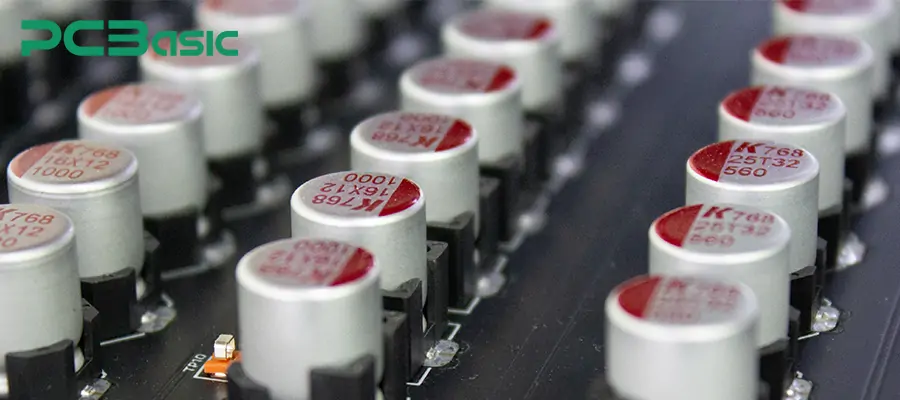
Modern electronic devices widely use SMD capacitors. However, identifying these capacitors is more challenging. The codes of SMD capacitors can mainly be divided into two types: unmarked SMD capacitor codes and SMD tantalum capacitor codes.
Unmarked SMD capacitors such as SMD ceramic capacitors. Most of their sizes are extremely small and have no printed markings on the surface. In such cases, it is necessary to use a capacitor calculator, an LCR meter or a circuit schematic for verification.
SMD tantalum capacitors usually have a three-digit number or a numerical value followed by a voltage code. For example: 106 16V → 10,000,000pF = 10 μF, with a rated voltage of 16 V.
4. Polarity and Voltage Markings
Polarity and voltage markings are also a type of capacitor codes. Electrolytic capacitors and tantalum capacitors are polarized. Their positive and negative terminals must be connected correctly; otherwise, it may cause the capacitor to be damaged or even the circuit to burn out.
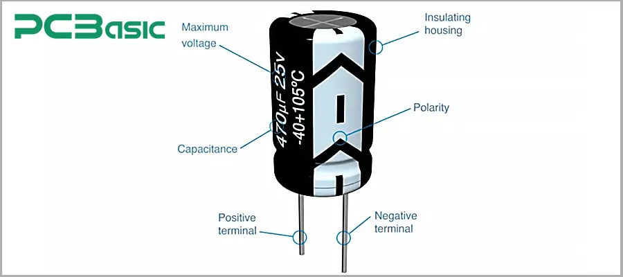
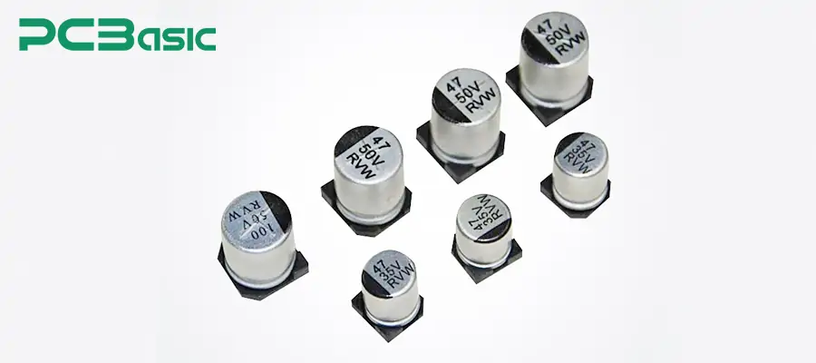
Positive electrode (anode): For the plug-in type, the pins are usually longer; for the surface mount type, it is mostly the side without the stripe.
Negative electrode (cathode): Usually indicated by stripes, a minus sign (−), or bold font.
Rated Voltage: Marked in forms such as 6V3, 10V, 16V, etc., indicating the maximum allowable direct current voltage.
Here, we will further explain the voltage codes, tolerance codes, and temperature characteristic codes. These extended identifiers are also crucial information regarding the performance of capacitors.
Capacitor Tolerance Codes
The capacitor tolerance code indicates the range of deviation between the actual capacitance of the capacitor and its nominal value. This parameter is particularly important for timing circuits, filters, and precision analog circuits, as even a small change in capacitance can affect the performance of the circuit.
Common tolerance codes:
E = ±0.5%
F = ±1%
G = ±2%
J = ±5%
K = ±10%
M = ±20%
High-precision circuits usually employ low-tolerance capacitors (such as F or G grades), while general-purpose circuits can use K or M grades of capacitors.
Capacitor Voltage Codes
The voltage code indicates the maximum DC voltage that the capacitor can safely withstand. This is particularly important for tantalum capacitors and electrolytic capacitors, as they are highly sensitive to overvoltage and polarity reversal.
Voltage code example:
6V3 → 6.3 V
16V → 16 V
When in use, the working voltage must be lower than the rated value, and a certain margin for reduction should be reserved in high-temperature or high-frequency applications to prevent leakage, overheating or damage.
Capacitor Temperature Characteristics Codes
Temperature characteristic code describes the variation pattern of capacitor's capacitance under different operating temperatures. Common temperature characteristic codes:
|
Temperature Code |
Characteristics |
Typical Applications |
|
C0G / NP0 |
Ultra-stable, minimal capacitance change with temperature |
RF circuits, high-precision filters and oscillators |
|
X7R |
Moderate stability from -55 °C to +125 °C |
General-purpose electronics, industrial control |
|
Y5V |
Large capacitance variation with temperature |
Low-cost or non-critical applications such as consumer electronics |
Mastering the tolerance codes, voltage codes and temperature characteristic codes can ensure that the capacitor operates stably, safely and reliably under the expected electrical and environmental conditions.
Correctly reading capacitor markings is of vital importance for selecting the right components, troubleshooting circuit faults, and ensuring the reliability of PCB assembly. So, how can we accurately interpret capacitor markings in practical applications? Previously, we introduced the types of capacitor codes and some examples. Now, we will explain to you the steps for accurately interpreting capacitor codes in practical applications.
Step 1
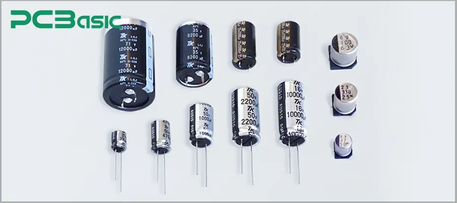
First of all, we need to carefully examine the surface of the capacitor to look for numbers, letters, color bands or polarity stripes.
For larger capacitors, such as tantalum capacitors and electrolytic capacitors, the capacitance, tolerance and rated voltage are usually directly printed on them.
Most SMD ceramic capacitors are very small in size and have no markings at all. They need to be identified through subsequent methods.
Step 2
After finding the surface label, we need to first determine which encoding format the capacitor uses. According to the previous introduction, there are mainly four types:
Numeric Codes, such as 104 or 223
Alphanumeric Codes, such as 473K
Capacitor Color Codes, using similar color bands to those of resistors
SMD Capacitor Codes, which may be numbers, voltage markings, or completely without labels
After confirming its encoding system, we can proceed with the subsequent interpretation. Confirming the encoding system first can prevent misjudging the capacitor value.
Step 3
After determining the coding system, one can interpret the capacitance values based on the corresponding coding types. We have already explained the interpretation methods for each type before.
Step 4
Most capacitor codes also include tolerance and rated voltage information:
Tolerance Codes: J = ±5%, K = ±10%, M = ±20%
Voltage Markings: Such as 6V3, 10V, 50V, indicating the maximum allowable direct current voltage
For polarized capacitors, such as tantalum capacitors or electrolytic capacitors, the polarity must also be confirmed. Stripes or a minus sign (−) indicate the negative terminal.
Step 5
If the capacitor has no label, the label is blurry or difficult to identify, tools can be used to confirm. Use a capacitance calculator or an LCR meter to measure the actual capacitance.
Through this, various capacitor codes can be quickly and accurately read, whether it is ceramic capacitor, film capacitor, SMD surface mount capacitor, or polar capacitor.
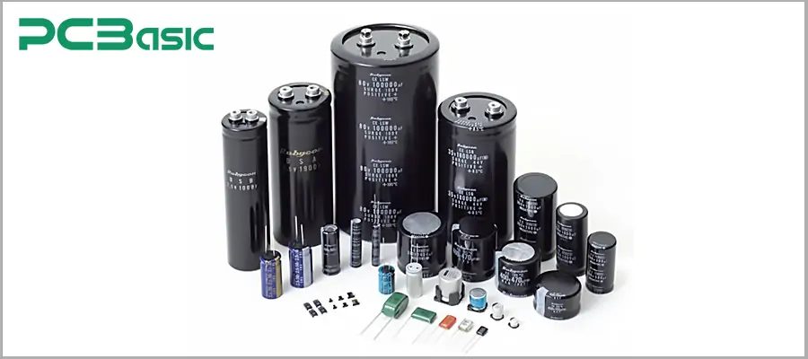
From circuit design, prototype development to mass production and later maintenance, all processes rely on the accurate interpretation of capacitor markings. The application of capacitor codes is very extensive. Here are the common scenarios of capacitor codes:
1. During the circuit design and prototype development stage, engineers highly rely on capacitor codes and capacitor value charts to select the appropriate components. Precise component selection is essential to ensure that timing circuits, signal filtering, and decoupling networks operate as intended. Moreover, the proper use of capacitor labels can save debugging time.
2. During the PCB assembly and production stages, especially when using SMD surface mount capacitors, accurately interpreting the capacitor codes is of utmost importance. Since many small-sized SMD capacitors have no markings, the production team relies on the SMD capacitor codes, BOM lists, and capacitor code tables to ensure that the components are correctly placed.
3. In the maintenance, repair and troubleshooting of electronic products, it is also necessary to quickly read and interpret capacitor codes. Technicians often use capacitor calculators, SMD capacitor codes and capacitor value reference tables to quickly determine the specifications of replacement components.
In a word, mastering capacitor codes is a basic skill for electronic engineers, technicians, and enthusiasts. Correct capacitor selection can ensure that the entire electronic workflow, from design, production to maintenance, is more efficient and reliable. Quickly interpreting capacitor codes not only guarantees the stability and lifespan of the project, but also saves time, reduces costs, and improves the overall design and maintenance efficiency. Below are some common capacitor identification codes that we have summarized. These can help you practice interpreting capacitor codes.
|
Capacitor Code |
Capacitance (pF) |
Capacitance (µF) |
Common Tolerance |
Typical Rated Voltage |
|
102 |
1,000 |
0.001 |
J (±5%), K (±10%) |
16V / 25V |
|
103 |
10,000 |
0.01 |
J, K, M (±20%) |
16V / 50V |
|
104 |
100,000 |
0.1 |
J, K, M |
25V / 50V |
|
223 |
22,000 |
0.022 |
J, K |
25V / 50V |
|
224 |
220,000 |
0.22 |
K, M |
25V / 50V |
|
334 |
330,000 |
0.33 |
K, M |
50V |
|
474 |
470,000 |
0.47 |
K, M |
50V / 100V |
|
105 |
1,000,000 |
1 |
K, M |
50V / 100V |
|
106 |
10,000,000 |
10 |
K, M |
6.3V / 16V / 25V |
Have you mastered the identification of capacitor codes? If you have any questions, please feel free to contact us.
 About PCBasic
Time is money in your projects – and PCBasic gets it. PCBasic is a PCB assembly company that delivers fast, flawless results every time. Our comprehensive PCB assembly services include expert engineering support at every step, ensuring top quality in every board. As a leading PCB assembly manufacturer, we provide a one-stop solution that streamlines your supply chain. Partner with our advanced PCB prototype factory for quick turnarounds and superior results you can trust.

Assembly Enquiry
Instant Quote
Phone contact

+86-755-27218592
In addition, we've prepared a Help Center. We recommend checking it before reaching out, as your question and its answer may already be clearly explained there.
Wechat Support

In addition, we've prepared a Help Center. We recommend checking it before reaching out, as your question and its answer may already be clearly explained there.
WhatsApp Support

In addition, we've prepared a Help Center. We recommend checking it before reaching out, as your question and its answer may already be clearly explained there.
