Global high-mix volume high-speed PCBA manufacturer
9:00 -18:00, Mon. - Fri. (GMT+8)
9:00 -12:00, Sat. (GMT+8)
(Except Chinese public holidays)
Global high-mix volume high-speed PCBA manufacturer
9:00 -18:00, Mon. - Fri. (GMT+8)
9:00 -12:00, Sat. (GMT+8)
(Except Chinese public holidays)
HomePage > Blog > Knowledge Base > Radar PCB: Everything You Need to Know About Design, Materials, and Applications
Radar technology was initially used only in military and aerospace fields. Now, with the continuous development of the electronics sector, radar technology has expanded into numerous fields such as automobiles, industry, communication, and weather monitoring. Radar PCB has become a crucial foundation in advanced sensing, detection, and communication technologies. For example, weather radar PCBs can accurately track storms and rainfall; the radar circuits in automobiles can achieve collision warning, adaptive cruise control, and automatic parking functions. These applications all rely on high-performance radar PCBs manufactured with advanced materials and strict design standards.
Today, we will comprehensively explain radar PCB in this article. We will introduce to you the definition, key characteristics, types, advantages, applications, material selection, design points and other aspects of radar PCB. So, what is a radar PCB?
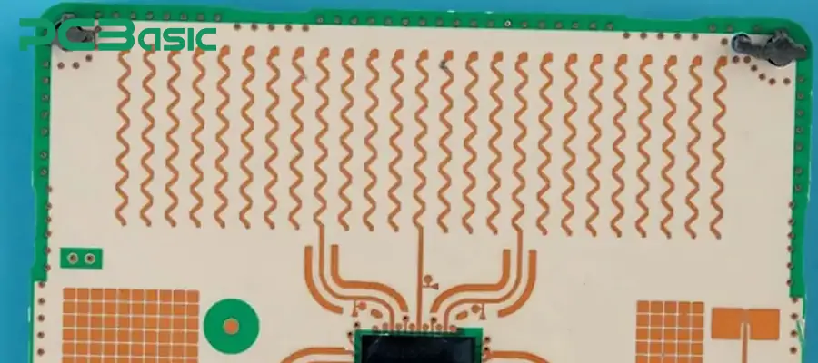
The radar PCB is a highly specialized printed circuit board. Because it is specifically designed to handle high-frequency and microwave signals in the "radar system", it is called "radar" PCB. The working frequency of the radar PCB for processing signals can extend to the gigahertz (GHz) range. This range enables the circuit board to transmit radar signals with extremely low distortion and signal loss, thereby ensuring the high accuracy of the radar system in detection, measurement, and target tracking.
From a system perspective, the radar PCB is not only a platform for carrying components, but also the core component of the radar circuit. In a radar circuit, the radar PCB must:
Maintain consistency in impedance to prevent reflection and standing waves;
Provide a low-loss transmission channel to ensure the stability of the signal at high frequencies;
Reduce environmental interference to ensure the high accuracy performance of the radar system in target detection, navigation, and measurement.
Without a carefully designed and manufactured radar PCB, even the most advanced radar chips and algorithms cannot achieve the desired performance.
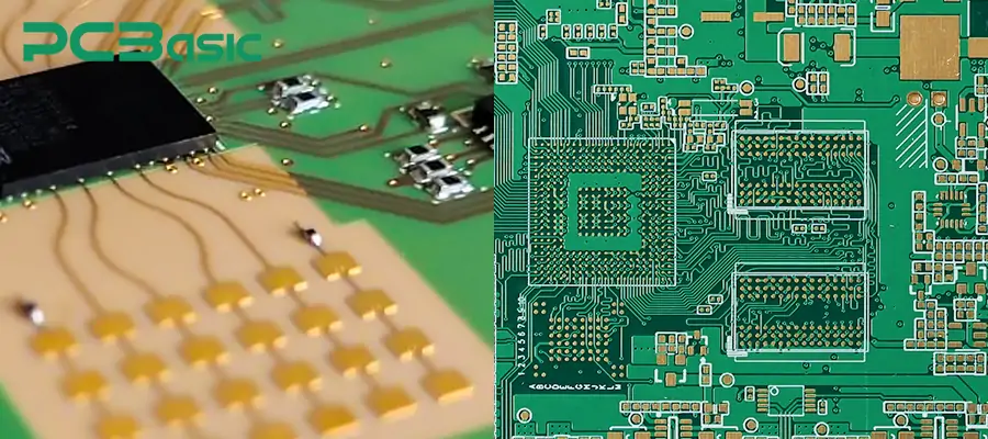
Unlike the low-frequency signal transmission standards used in consumer electronics, radar PCBs require special materials, strict impedance control, and advanced manufacturing techniques for production. The following table lists the key differences between standard PCBs and radar PCBs. After reading it, you will have a clearer understanding of these two types.
|
Aspect |
Standard PCB |
Radar PCB |
|
Signal Frequency |
Mainly used for low- or mid-frequency signals (such as audio, video, or digital data), typically operating in the kHz–MHz range |
Designed for microwave and millimeter-wave bands (1–300 GHz). Extremely sensitive to high-frequency signals where even small errors can impact performance |
|
Material Selection |
Commonly uses FR4 laminate, which is cost-effective but has high dielectric loss at GHz frequencies |
Uses low-loss dielectric materials such as PTFE composites, Rogers laminates, or ceramic-based materials to ensure signal integrity |
|
Design & Manufacturing |
Wider tolerance, lower impedance control requirements |
Requires strict impedance control, precise layer stack-up, and advanced plating/etching techniques to avoid signal reflection and phase errors in radar circuits |
Radar technology is constantly breaking through traditional military and aerospace applications and is playing an increasingly significant role in the electronics field. It can be said that radar PCBs are the core of advanced systems such as weather monitoring, automotive safety, and industrial automation nowadays. For example, in the field of weather monitoring, weather radar PCBs can maintain high-frequency accuracy and stability in an environment with constantly changing temperature and humidity. This ensures the long-term reliability of storm detection, rainfall measurement, and climate research data.
In the automotive industry, radar PCBs are the key support for ADAS systems, used for collision warning, lane change assistance, and adaptive cruise control functions. The radar circuit boards in these systems not only have lightweight, miniaturized, and real-time signal processing capabilities, but also minimize interference as much as possible.
In conclusion, radar PCBs are no longer a niche application but an indispensable key component in modern electronics. They have driven rapid innovation in multiple industries.
The performance requirements of the radar system for the circuit board are much higher than those of ordinary circuits. The unique advantages of the radar PCB in terms of performance can be analyzed from the following aspects.
1. The radar PCB is specifically designed for high-frequency applications. Its operating frequency is usually in the microwave frequency range of the GHz level. This capability enables it to process radar signals with extremely high precision, making it widely applicable. For example, it is often used in automotive ADAS systems and air traffic control.
2. Signal integrity is crucial for radar circuits. The radar PCB achieves low-loss transmission through controlled impedance routing, carefully designed stack-up structure, and high-quality copper plating. This design effectively reduces signal reflection, attenuation, and electromagnetic interference, ensuring the accuracy and reliability of radar signals during long-distance transmission. This characteristic makes radar PCBs widely used in weather monitoring and defense systems.
3. Modern applications (such as autonomous vehicles, satellites, and airborne radar platforms) require PCBs to be compact and lightweight. The advanced multilayer circuit design and flex-rigid structure adopted by radar PCBs can integrate complex radar electronic circuits in a limited space without affecting performance. This feature can well meet the changing requirements of modern applications.
4. Radar PCBs are also very stable and reliable in extreme environments such as high temperatures, humidity, vibration, and even radiation. This is because to ensure long-term stable operation, manufacturers use special protective coatings, metal core substrates, and reinforced designs, enabling them to withstand harsh conditions without performance degradation. The reliability of radar PCBs makes them an indispensable key component in military radar, avionics, and weather radar systems.
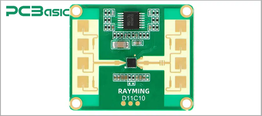
The design of radar PCBs is not uniform; instead, it is customized according to different radar applications. Depending on the working frequency, signal processing requirements, and usage environment, various types of radar PCBs can be developed. Here are several common types of radar PCBs:
Doppler radar PCB
Doppler radar PCB is widely used in motion sensing and speed measurement. It analyzes the frequency shift between the transmitted and received radar signals to accurately detect the speed of moving objects. Common applications include automotive speed radar, industrial automation sensors, and even life-sign monitoring in medical equipment. The circuit board design emphasizes the stability of high-frequency signals and low-noise circuits to ensure precise motion detection in real-time environments.
Single-pulse radar PCB
Single-pulse radar PCB is mainly used for high-precision tracking. Unlike traditional radars that require multiple scans, single-pulse radars can calculate the position of the target with a single pulse, making them ideal for missile guidance, air defense systems, and advanced surveillance radars. Such PCBs require extremely low-loss transmission lines and controlled impedance design to ensure the accuracy of angle resolution. At the same time, their compact multilayer structure also facilitates integration into military and aerospace platforms, ensuring high precision while maintaining reliability.
Meteorological radar PCB
Meteorological radar PCB is specifically used for meteorological detection, such as rainfall monitoring, storm tracking, and long-term climate monitoring. They need to handle high-power microwave signals and maintain signal integrity over long distances. Since these radars operate outdoors all year round, they must withstand high humidity, temperature changes, and electromagnetic interference. Therefore, they are usually made with durable substrates and protective coatings to ensure long-term stable performance.
ADAS radar PCB
ADAS radar PCB is one of the fastest-growing applications. They are integrated into collision warning systems, blind spot detection, adaptive cruise control, and autonomous driving platforms. ADAS radars typically operate in the 24 GHz or 77 GHz frequency bands, which pose higher requirements for PCB miniaturization design, flex-rigid combined structure, and lightweight materials.
Military and aerospace radar PCB
Military and aerospace radar PCB is the category with the highest requirements for performance and reliability. They are used in surveillance systems, airborne radars, missile tracking, and space exploration. Such PCBs must be able to withstand intense vibration, radiation, and extreme temperature changes. In manufacturing, this PCB often uses metal core substrates, low-loss laminates, and advanced shielding technologies.
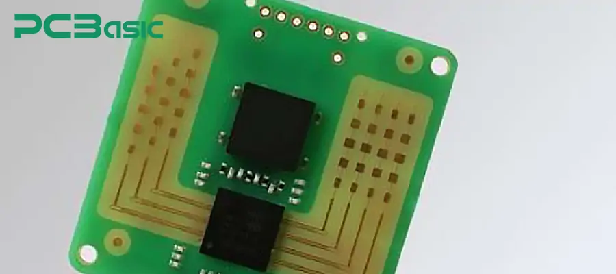
Although there are various types of radar PCBs, their performance and value share some common advantages. These advantages not only enable radar PCBs to be widely used in industries such as automobiles, aerospace, military, defense, and meteorology, but also lay the technical foundation for future intelligent transportation, 5G radar, and autonomous driving.
1. One of the most prominent advantages of radar PCB is its ability to maintain stable signal transmission even in high-frequency and microwave environments. This advantage helps achieve high-precision detection and measurement of targets by the equipment. The precise measurement of radar PCB directly determines the reliability of the radar system and the success rate of mission execution. For example,
In military radar, this high-precision capability enables the system to accurately distinguish between targets and interference, and precisely locate the positions of aircraft, missiles or ships.
In aerospace applications, this advantageous performance helps satellites and aircraft achieve precise positioning and trajectory correction, ensuring the reliability of navigation in complex space environments.
In civil aviation, the high-precision detection capability is used in air traffic control radars to ensure the safety and efficiency of flight scheduling.
2. Another significant advantage of the radar PCB is its high degree of application adaptability. This wide adaptability is attributed to its customizable material selection, stack-up structure, and processing techniques. This advantage enables it to flexibly meet the requirements of different scenarios. For instance,
In the automotive field, radar PCBs can support ADAS systems, including blind spot detection, automatic parking, and collision warning.
In meteorological monitoring, they support high-power radar systems, providing real-time tracking of rainfall and storms.
In industry and the Internet of Things (IoT), radar PCBs are integrated into intelligent sensors, used to enhance automation levels in intelligent transportation, intelligent factories, and logistics systems.
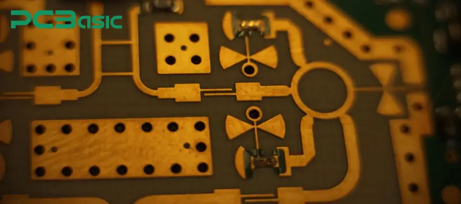
3. With the continuous development of 5G communication, millimeter wave technology and MIMO radar, radar systems are moving towards higher bandwidth, faster response speed and greater intelligence. This compatibility ensures that radar PCBs are not only suitable for existing technologies but also can smoothly transition to future emerging applications.
They can support phased array radar, enabling simultaneous tracking of multiple targets and rapid scanning.
In 5G radar systems, radar PCBs can provide low-loss high-speed signal transmission, meeting the requirements of high-frequency communication and high-speed processing.
In autonomous driving platforms, radar PCBs work in conjunction with cameras, lidar and other sensors to help achieve comprehensive environmental perception of vehicles.
4. Even in extreme conditions such as high temperatures, low temperatures, high humidity, strong vibrations, and even radiation, radar PCBs can remain stable for a long time. For instance, in aerospace, radar PCBs need to operate stably for a long time in high-altitude or space environments, resisting drastic temperature changes and radiation impacts. In the defense sector, military radar PCBs need to withstand high-intensity vibrations and impacts while ensuring circuit integrity. In weather radar, they must maintain efficient operation for long periods in windy, lightning, and humid environments.
These advantages of radar PCBs are all influenced by the materials used.
The selection of materials plays a crucial role in the performance of radar PCBs. Depending on different cost requirements, power demands and application scenarios, the materials used can also vary. The following table summarizes several of the most commonly used types of materials in radar PCB manufacturing, along with their main characteristics, advantages, limitations and typical applications. Let's take a look together!
|
Material Type |
Examples |
Key Features |
Advantages |
Limitations |
Typical Applications |
|
Epoxy-based Laminates |
FR4 (standard PCB material) |
Glass-fiber reinforced epoxy resin |
- Low cost - Mature manufacturing process - Easy to process |
- Limited high -frequency performance - Higher signal loss - Unstable dielectric constant |
Low-frequency radar prototypes, cost-sensitive applications |
|
High-frequency Laminates |
PTFE (Teflon), Hydrocarbon ceramics |
Designed for high-frequency and microwave applications |
- Stable dielectric constant - Very low loss - Frequency range up to GHz–mmWave |
- Difficult to process - Higher cost |
Millimeter-wave radar, ADAS radar, phased-array radar |
|
Low-loss Dielectric Materials |
Rogers (RO4000, RO3000), Taconic, Isola |
Commercial laminates optimized for low loss and high frequency |
- Excellent high -frequency performance - Controlled dielectric constant - Good compatibility with standard processes |
- More expensive than FR4 - Limited suppliers |
Aerospace radar, 5G radar systems, high-precision radar |
|
Metal-backed Substrates |
Aluminum-backed, Copper-backed |
Metal base enhances thermal management |
- High thermal conductivity - Strong mechanical strength - Suitable for high -power circuits |
- Higher cost - More complex fabrication |
High-power weather radar, military radar, systems with strict heat dissipation requirements |
The performance of the radar system largely depends on the quality of the PCB. Compared to conventional PCBs, the design and manufacturing process of radar PCBs require stricter standards and specialized techniques. Below, we have summarized the key design points and manufacturing process of radar PCBs.
The key points of radar PCB design are to ensure signal integrity, reduce losses and prevent interference. So how to do it?
Firstly, controlled impedance. Because at high frequencies, even a tiny deviation in the line width or dielectric constant can cause reflection and signal distortion. Therefore, the impedance must be precisely calculated during the design. This process can be verified through simulation tools such as HFSS and ADS.
Secondly, the stack-up should be reasonable. Suggestion:
In a multilayer stacked structure, the signal layer is alternately arranged with the ground layer and the power layer. This enables effective isolation.
Placing the ground layer close to the signal layer can reduce the circuit area and lower electromagnetic radiation.
Thirdly, pay attention to grounding and shielding. Noise can directly affect the accuracy of the radar PCB. We can reduce crosstalk through via stitching, guard traces, and shielding cavities. This is very helpful for the accuracy of the radar PCB.
Fourthly, pay attention to thermal management. The radar module generates a large amount of heat during operation. If not managed properly, it is very likely to cause serious consequences. Therefore, during the design process, we need to pay attention to using heat-conductive vias and large-area copper foil to help dissipate heat and prevent components from overheating.
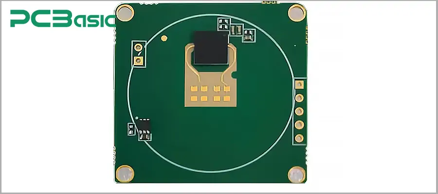
The manufacturing process of radar PCB is more complex than that of ordinary circuit boards, and the control of dimensions, materials, and process conditions is also more stringent. The standard manufacturing process of radar PCB is as follows: design and engineering preparation → substrate processing → inner layer circuit fabrication → lamination → drilling and metallization → outer layer circuit formation → surface treatment → soldering mask application → surface coating/surface treatment → assembly and testing → final testing and quality inspection. During these processes, we need to pay attention to:
1. The requirements for materials for radar PCBs are much higher than those for ordinary circuit boards. For instance, to achieve high-frequency signals in radar PCBs, low-loss and low-hygroscopicity substrates must be selected, such as PTFE, Rogers series, Taconic or ceramic-filled composite materials. These materials can effectively reduce signal attenuation and ensure high-fidelity transmission of radar signals in GHz and even millimeter wave frequency bands.
2. During manufacturing, precise etching processes and layer control are necessary to ensure impedance consistency, so that high-speed radar signals can remain intact during transmission.
3. During the lamination process, the heating rate, pressure and curing time must be precisely controlled. Otherwise, the board may separate, have bubbles or unstable dielectric properties. The lamination process for radar PCBs is more stringent and requires the use of special bonding sheets or low-viscosity resins to ensure structural integrity.
4. Common blind holes, buried holes and micro-blind holes in radar PCB design are usually completed by laser drilling. The hole diameters may only be a few tens of micrometers. It is important to note that the metalization electroplating process after drilling must ensure uniform coating on the hole walls and strong adhesion, otherwise it will lead to high-frequency signal loss or even circuit open circuits.
5. During manufacturing, large-area copper foil, thermal vias and metal back plates are usually designed to enhance thermal conductivity. Some applications may also combine heat sinks or liquid cooling solutions to ensure the long-term stable operation of radar circuits.
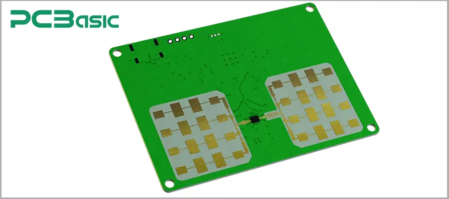
6. The surface treatment of radar PCBs not only affects the soldering performance but also directly relates to the high-frequency characteristics. Common ENIG, ENEPIG and silver plating processes can provide a smooth and flat surface, reducing the influence of contact resistance and surface roughness on the signal.
7. Radar PCB components include surface mount devices and may also have high-power devices that require through-hole soldering. In mixed welding, to avoid the impact of high temperatures on surrounding sensitive components, selective wave soldering or automatic welding equipment is usually used to ensure firm and reliable solder joints.
8. Traditional AOI, X-ray inspection and ICT can only ensure the basic processing quality of the circuit. Radar PCBs must also undergo specialized RF testing. For example, insertion loss testing, return loss (S11 parameter) testing, reliability assessment, etc. These verification steps can ensure the stability of the PCB's performance in high-frequency working environments and meet the strict requirements of aerospace, military and automotive radars.
Even with the adoption of advanced design and manufacturing techniques, radar PCBs may still experience failures in practical applications. Understanding the failure analysis and testing methods related to radar PCBs is beneficial for their long-term reliability. In the following table, we summarize the common failure modes of radar PCBs, the corresponding testing methods, and preventive measures:
|
Category |
Details |
|
Common Failure Modes |
- Delamination: Layer separation due to poor lamination, thermal cycling, or moisture ingress. - Overheating: Excessive heat in high-power sections damages dielectric materials and shortens lifespan. - Signal degradation/loss: Impedance mismatch, microcracks, or material aging reduce radar accuracy. - Electromigration: Conductive paths form under high humidity/voltage, causing short circuits. |
|
Testing Methods |
- RF performance tests: S-parameters, VSWR, insertion loss for high-frequency validation. - Functional testing: Simulates radar operation to check transmit/receive paths and overall performance. - Reliability evaluation: Thermal shock, temperature cycling, humidity, vibration tests for long-term durability. - X-ray/cross-section: Detects voids, cracks, poor plating inside vias and solder joints. |
|
Preventive Measures |
- Material selection: Use low-loss, high-reliability laminates (e.g., PTFE, Rogers, Isola, Taconic). - Optimized design rules: Proper stack-up, impedance matching, robust grounding, and thermal management. - Strict process control: Follow IPC/ISO standards with in-line monitoring and SPC (Statistical Process Control). - Enhanced inspection: AOI, flying probe, and RF testing during production to catch issues early. |
From design principles to manufacturing processes, and then to failure analysis and preventive measures, the production process of radar PCBs is far more complex than that of ordinary circuit boards. Whether in the design stage, the production process, or the performance testing, every step is closely related to the accuracy, stability, and safety of the radar system.
 About PCBasic
Time is money in your projects – and PCBasic gets it. PCBasic is a PCB assembly company that delivers fast, flawless results every time. Our comprehensive PCB assembly services include expert engineering support at every step, ensuring top quality in every board. As a leading PCB assembly manufacturer, we provide a one-stop solution that streamlines your supply chain. Partner with our advanced PCB prototype factory for quick turnarounds and superior results you can trust.

Assembly Enquiry
Instant Quote
Phone contact

+86-755-27218592
In addition, we've prepared a Help Center. We recommend checking it before reaching out, as your question and its answer may already be clearly explained there.
Wechat Support

In addition, we've prepared a Help Center. We recommend checking it before reaching out, as your question and its answer may already be clearly explained there.
WhatsApp Support

In addition, we've prepared a Help Center. We recommend checking it before reaching out, as your question and its answer may already be clearly explained there.
