Global high-mix volume high-speed PCBA manufacturer
9:00 -18:00, Mon. - Fri. (GMT+8)
9:00 -12:00, Sat. (GMT+8)
(Except Chinese public holidays)
Global high-mix volume high-speed PCBA manufacturer
9:00 -18:00, Mon. - Fri. (GMT+8)
9:00 -12:00, Sat. (GMT+8)
(Except Chinese public holidays)
HomePage > Blog > Knowledge Base > PCB Headers: The Ultimate Guide
Stable connection performance is as important as advanced processors, precise components and good PCB design. Whether it is a compact IoT sensor, a rugged industrial control device or a high-speed communication module, every product ultimately relies on a reliable and maintainable electrical interface. And PCB Header is a key part of this.
These connectors are not merely "metal pins inserted into the board". They are the fundamental channels for signal, power supply and data transmission within the system. They affect the maintainability, modularity of the equipment, and the convenience of hardware during testing, expansion or connection with external accessories. Therefore, the correct selection of PCB header pins is very important. Next, this article will explain the relevant content about PCB headers to you.
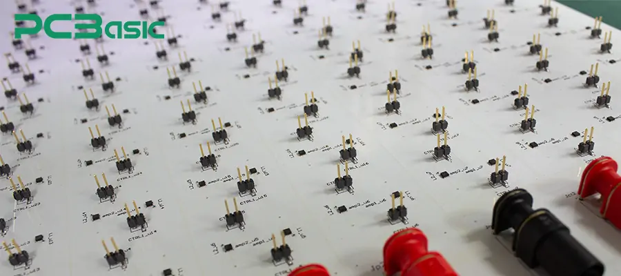
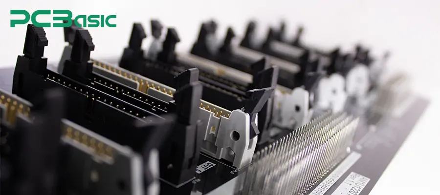
The PCB header (also known as PCB header connector, pin header or PCB pin header) is a set of metal pins arranged at fixed intervals. When soldered onto the PCB board, it can be used to achieve electrical and mechanical connections. In the field of electronic manufacturing, engineers often use these interface pins to connect two boards together, connect wiring harnesses, connect external sensors, etc.
Although the PCB header may seem to have a simple structure, it performs multiple crucial functions in electronic products:
Modular connection
Through pin headers, subboards, expansion cards, sensors, display modules, etc. can be plugged and unplugged without soldering, achieving a truly modular design.
Mechanical Support
When the PCB header pins are aligned with the corresponding header connectors or wiring harnesses, a stable and firm mechanical connection can be formed. It is resistant to vibration and impact and is suitable for applications in automobiles, industrial equipment, and portable devices.
Testing and Programming Interface
Engineers often use PCB headers to connect UART, SWD, ISP, JTAG, I²C, SPI and other debugging and programming signals, making firmware burning, debugging and board-level verification more convenient.
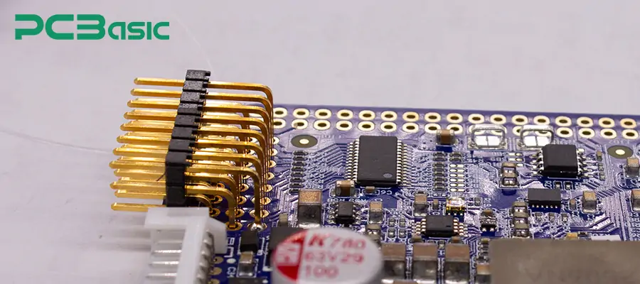
In the process of prototype development and mass production, choosing to use PCB header pins or pin header connectors offers several advantages, which are as follows:
1. PCB header connectors are inexpensive, come in various specifications, and are readily available in stock from major distributors. Thus, the procurement process is extremely convenient.
2. The PCB headers can be customised to a high degree. Whether it's single-row, double-row, direct mounting, side insertion, with protective sleeves, or with special spacing, there are corresponding types available on the market.
3. The pin headers adopt standardised spacing and pad designs. The design is simple, and it is very easy to draw the package, with little chance of errors.
4. PCB pin headers can be matched with patch cords, IDC terminals, wiring harnesses, and numerous header connector series, and are compatible with various connector systems.
5. High-quality PCB headers can withstand multiple insertions and extractions, and are durable and reliable.
Overall, PCB headers are one of the most widely used, highly flexible and commonly adopted connection solutions by engineers at present.
To accommodate various mechanical, electrical, assembly methods and environmental conditions, PCB headers come in many different types. Below, we will introduce them from several aspects such as the number of rows and orientation. Here are the common types of PCB headers:
|
Classification |
Type |
Key Features |
Common Applications |
|
Orientation |
Straight / Vertical |
Vertical mating, simple structure |
Development boards, module interfaces |
|
Right-Angle |
Side-exit connection, space-saving |
Compact enclosures, communication modules |
|
|
Row Count |
Single-Row |
Low cost, easy to use |
Sensors, Arduino-style boards |
|
Dual-Row |
Higher density, compact |
Raspberry Pi, industrial control boards |
|
|
Multi-Row |
Very high density, large pin counts |
Automotive ECUs, backplane and rack systems |
|
|
Housing Style |
Unshrouded |
Bare pins, lowest cost |
General electronics, prototypes |
|
Shrouded / Box Header |
Keyed mating, protected housing |
IDC ribbon cable systems |
|
|
Locking Header |
Retention latch, prevents accidental unplugging |
Automotive, vibration-prone devices |
|
|
Mounting Method |
Through-Hole |
High mechanical strength, vibration resistant |
Industrial control, automotive hardware |
|
SMD Header |
SMT mounting, compact layout |
IoT devices, miniaturized PCB designs |
|
|
Special Function |
IDC / Waterproof / High-Current |
Specialized performance and environmental resistance |
Industrial equipment, communication modules, outdoor devices |
The termination method of PCB headers will affect the assembly speed, connection reliability, mechanical strength, and long-term maintenance performance. When choosing PCB headers, engineers usually take the termination method, along with factors such as pitch, number of rows, and housing type, into consideration. Here are several of the most commonly used termination methods for PCB headers:
1. Through-Hole Soldering
The Through-Hole connection method is a traditional process: PCB header pins pass through the metallized holes on the PCB and are then soldered on the other side of the board.
Main features:
a. The mechanical strength is the highest. Due to the pins penetrating the circuit board, THT pin header connectors can withstand greater tension, vibration and frequent plugging and unplugging.
b. Suitable for high-stress environments. For instance, in industrial control systems, automotive ECU, power modules, THT header connectors can offer greater reliability.
c. Commonly used in power supply and I/O interfaces.
2. Surface Mount Technology (SMT)
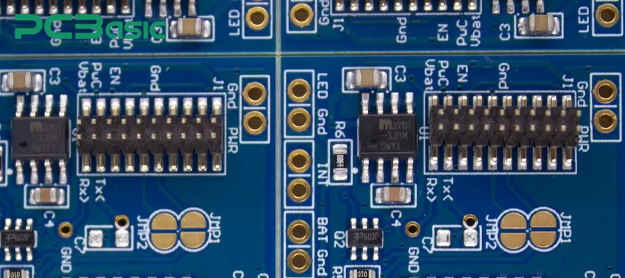
The pads of the PCB header connectors directly lie on the surface of the PCB, without the need for vias. The connection can be firmly fixed through reflow soldering.
Main features:
a. Supports fully automatic SMT process. SMT pin headers can be placed by the reflow machine and reflow-welded together with other SMD components. This method reduces the number of manual assembly steps.
b. Occupies less board area and has a lighter structure. SMT pin headers do not require vias, which helps save space on the circuit layer and is suitable for high-density layouts and small designs.
c. Perfectly suitable for compact consumer electronics.
However, with this type of connection method, there are limitations on mechanical strength, and it is not as stable as THT when subjected to axial tension.
3. Press-Fit Termination
The press-fit PCB header pins feature a unique geometric structure, which can be directly inserted into the metallized holes of the PCB without the need for soldering. The pins form a gas-tight and highly reliable contact with the hole walls.
Main features:
a. No soldering required. The compression connection method eliminates the soldering step, avoiding soldering defects and is highly favored in high-reliability systems.
b. Suitable for high-reliability connections in critical mission systems.
c. Commonly found in automotive and server hardware.
However, Press-fit termination requires precise hole diameter tolerances and press-fit applicator. The initial design work is quite extensive.
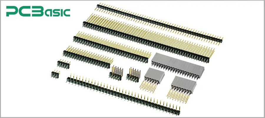
The pins used for PCB pin headers are usually made of copper alloy, as copper alloy has excellent conductivity and mechanical strength. To enhance durability and reduce oxidation, different electroplating treatments are applied to the surface of the pins.
Common electroplating methods include:
Tin Plating
Gold Plating
Insulating material / Enclosure material
Common materials include:
PBT, which has excellent mechanical strength and stable heat resistance.
PA6T / PA9T, often used in fine pitch connectors.
LCP, with excellent dimensional stability and very low moisture absorption rate.
High-quality contact materials can ensure that the pins remain in a stable position, achieve a good connection, and maintain reliable performance during the soldering process.
The current-carrying capacity of the PCB header pins depends on the pin size, pitch, electroplating material, and the heat dissipation environment.
Fine pitch signal type pin headers (0.8mm – 1.27mm): Usually 1A – 2A
Standard 2.54mm PCB headers: Usually 3A – 5A
Heavy-duty power header connectors: With thickened pins, can reach 8A – 10A or higher
Choosing the correct current specification can prevent excessive heating and ensure stable operation over the long term.
The operating temperature range for most standard PCB header connectors is from –40℃ to +105℃. However, specialized industrial-grade, automotive-grade or outdoor-grade pin headers can support temperatures of +125℃, +150℃, and even higher.
The rated voltage of the pin connector is determined by the following factors:
Pitch
Insulator material
Creepage distance and air gap
Pin geometry structure
The rated voltage range for common PCB pin headers is: 100V – 300V. Higher voltages require a greater creepage distance and a wider pitch between pins.
The pitch of the pins determines the center spacing between the pins and directly affects the size, current capacity, mechanical strength of the connector, as well as its compatibility with other components. The following table summarizes the most commonly used pitch standards for PCB header connectors in modern electronic products:
|
Pitch Size |
Key Features |
Typical Applications |
Notes / Keyword Usage |
|
2.54mm (0.1”) |
• Excellent mechanical strength • Easy to hand-solder and prototype • Higher current capability |
Arduino headers, Raspberry Pi HATs, development boards, industrial control modules |
Most common pin header connector pitch; standard for general-purpose PCB headers |
|
2.00mm |
• More compact than 2.54mm • Maintains good mechanical stability |
Consumer electronics, IoT modules, communication boards |
Popular mid-size pitch in modern PCB pin headers |
|
1.27mm |
• High-density layout • Suitable for low-profile interfaces • Good for digital signal connectors |
SWD programming headers, mezzanine boards, embedded systems |
Frequently used fine-pitch PCB header connectors |
|
1.00mm |
• Ultra-compact footprint • Lower current rating • Requires high-precision housings |
Wearables, portable electronics, mini IoT hardware |
Often built using LCP housings; miniature pin connector standard |
|
0.80mm |
• Extremely high density • Smallest mainstream pitch • Ideal for signal-level connections |
Mobile devices, micro-modules, tight-space electronics |
Increasingly used in ultra-compact PCB header connector types |
Due to its simple structure, diverse types and high flexibility, PCB headers are applied in almost all electronic industries.
In consumer products, space is limited and the design often requires flexible internal interconnection methods. PCB header connectors can provide compact and standardised interfaces, and are therefore commonly used in such products. Common applications include:
Connecting audio circuits to various sensors and subboards
Connecting power amplifier boards, signal interfaces, and control boards
Connecting power supply boards, control interface boards, and display function modules
The industrial environment requires high durability and long-term stable operation. PCB pin headers have high mechanical strength, strong modularity, and are easy to integrate, and are widely used in industrial control equipment. Common applications include motor controllers, PLC modules, and sensing and measurement devices.
Automotive electronic equipment must be able to withstand vibrations, temperature changes, and have high reliability standards. Header connectors are commonly used for:
ECU - Diagnostic pins, configuration jumpers interface
Vehicle entertainment system - Display module, data communication interface
ADAS module - Sensor board, internal signal distribution
High-density computing equipment requires reliable internal expansion and signal distribution methods. PCB headers are often used as standard interfaces within servers and workstations, for:
Backplanes - Signal distribution with high pin count
PCIe extenders/transceivers - Board-to-board stacking interfaces
Expansion boards - Debugging pins, auxiliary power/data interfaces
Although the PCB headers have a simple structure, if the design or handling is improper, it can still lead to electrical or mechanical failures. Common problems include:
1. Weak Solder Joints
When the solder joints do not have sufficient wetting, they may become weak and unreliable. This can lead to unstable signals, increased contact resistance, and even complete circuit breakage.
Solution:
Adjust the reflow soldering temperature or re-optimize the heat curve
Improve the design of the steel mesh openings to ensure consistent solder paste quantity
Ensure the compatibility of the electroplated layer with the solder
2. Pin Position Misalignment
Inaccurate positioning during assembly can result in difficult insertion or bent pins.
Solution:
Use SMD pins with staggered columns or surface-mountable sockets
Check the tolerance of the pad dimensions against the reference point design
Optimize the assembly method and the support of the jig
3. Bent or Damaged Pins
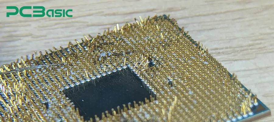
Transportation, assembly, or repeated insertion and removal may cause the pins to bend. Minor deformation may result in poor contact or sticking.
Solution:
Choose reinforced or thickened PCB header connectors
Use shielded pin headers to prevent external damage
Optimize the structural design of manual insertion and testing fixtures
4. Contact Oxidation
The tin-coated header pins may oxidize over time, causing the contact resistance to increase.
Solution:
Use gold-coated pins to enhance the anti-oxidation performance.
Avoid exposure to high humidity or contaminated environments.
For cost-sensitive scenarios, selective gold plating can be adopted.
5. Insufficient Mechanical Support
In the presence of mechanical forces or vibrations, a simple SMT structure may not be able to provide adequate support.
Solution:
Switch to plug-in (THT) PCB pin headers
Add reinforced structures or fixation points
Choose pin headers with sheaths to enhance alignment and support performance
Reasonable troubleshooting and design choices can ensure that the pin headers maintain good electrical contact quality and mechanical stability.
When making the selection, we should pay particular attention to these key points:
The PCB header may seem to have a simple structure, but it plays a crucial role in electronic manufacturing. By understanding different types of pin headers, termination methods, materials, electroplating structures, pitch specifications, and electrical/thermal characteristics, we can make more reasonable selections, reduce potential failure points, and enhance product reliability. Correctly choosing the appropriate pin connector can ensure stable signal transmission, solid mechanical support, smooth production and assembly, and maintain good maintainability throughout the product's entire lifecycle.
About PCBasic
Time is money in your projects – and PCBasic gets it. PCBasic is the pcb assembly company that delivers fast, flawless results every time. Our comprehensive PCB Assembly Services include expert engineering support at every step, ensuring top quality in every board. As a leading PCB Assembly Manufacturer, we provide a one-stop solution that streamlines your supply chain. Partner with our advanced PCB Prototype Factory for quick turnarounds and superior results you can trust.
Assembly Enquiry
Instant Quote
Phone contact

+86-755-27218592
In addition, we've prepared a Help Center. We recommend checking it before reaching out, as your question and its answer may already be clearly explained there.
Wechat Support

In addition, we've prepared a Help Center. We recommend checking it before reaching out, as your question and its answer may already be clearly explained there.
WhatsApp Support

In addition, we've prepared a Help Center. We recommend checking it before reaching out, as your question and its answer may already be clearly explained there.
