
Global high-mix volume high-speed PCBA manufacturer
9:00 -18:00, Mon. - Fri. (GMT+8)
9:00 -12:00, Sat. (GMT+8)
(Except Chinese public holidays)





HomePage > Blog > Knowledge Base > Servo Driver PCB Assembly: Manufacturing, Testing, and Reliability Guide
1. What Is a Servo Driver PCB and How Does It Work?
2. What Makes Servo Driver PCB Assembly Challenging?
3. Critical Controls During Servo Driver PCB Assembly
4. Inspection and Functional Testing of Servo Drive PCB Assemblies
5. From Prototype Servo Driver Boards to Reliable Volume Production
Take a typical servo driver board as an example. You will find that there are often many different types of components on it, such as control ICs, gate drivers, current-sensing circuits, encoder interfaces, power semiconductors, large capacitors and high-current connectors. Some components require very precise SMT assembly, while others will generate more heat, larger solder joints, and even require through-hole assembly. That is to say, even if the board looks fine after soldering, after the motor actually runs, it may still show overheating, unstable feedback or other functional abnormalities.
So, in the process of servo drive PCB assembly, which steps need to be carefully controlled? In this article, we will look at the basic structure of the servo driver board, introduce the main assembly challenges, key control points in SMT and through-hole processes, inspection and functional testing methods, and what needs to be confirmed before a servo drive PCB project moves from prototype to stable volume production.
The servo driver board can be regarded as the execution unit between the motion control system and the servo motor. After the controller issues position, speed or torque instructions, the driver board converts these instructions into electrical energy that can drive the motor. And meanwhile, it continuously reads feedback signals, then adjusts the output according to the actual operating status. In simple terms, it is always doing the "execution - feedback - correction" thing.
A typical industrial servo driver board usually includes an MCU or DSP, gate drive, current and voltage sensing, encoder or resolver interface, as well as communication interfaces such as CAN, RS-485, and EtherCAT. The entire working path can be understood as:
Command → Control processing → Gate drive → Power stage → Servo motor → Feedback → Correction
Some products integrate these functions on a single PCB, while others are split into servo drive control boards and servo drive power boards. As for the terms servo control board, servo motor controller board, and servo motor driver board, these may not be exactly the same in different products. For PCB manufacturing, there's no need to get too obsessed with the name actually, what is more important is to consider the actual circuit, power, components, and testing requirements.
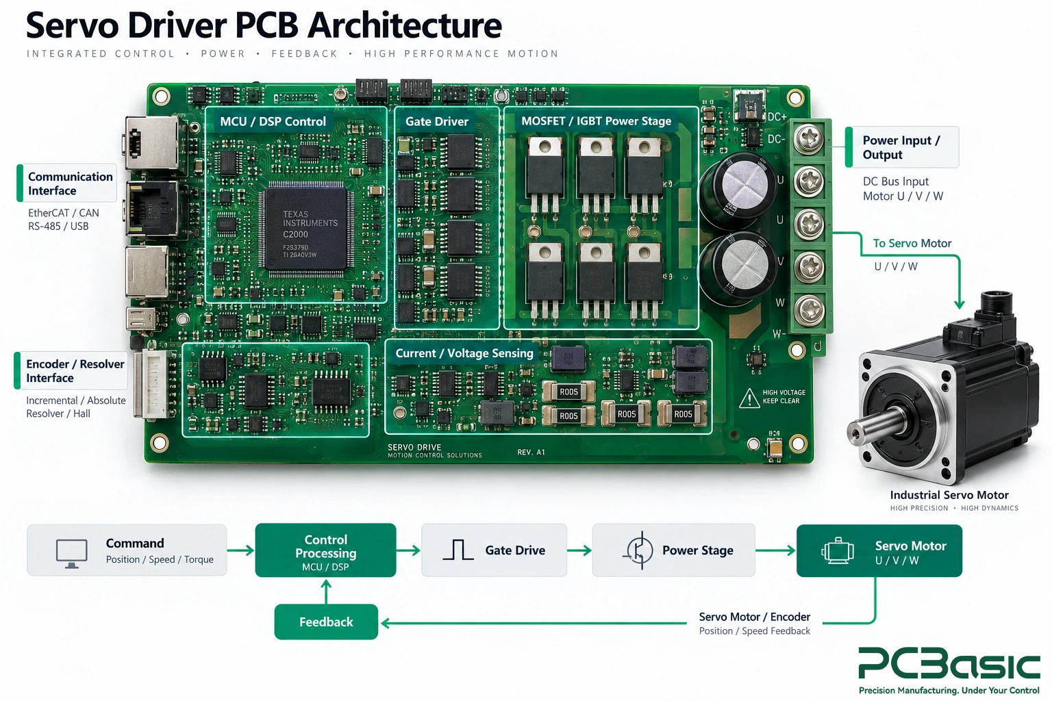
The difficulties in servo driver PCB assembly mainly arise from the fact that multiple circuits with completely different properties exist on the same circuit board. The power stage needs to handle a large amount of current and also generates heat and switching noise; while the current-sensing, encoder, communication, and control circuits typically process smaller signals and are more sensitive to interference. That is to say, a servo driver board needs to take into account power handling, signal integrity, thermal management, and isolation simultaneously.
The complexity of component types also increases the production difficulty. Fine pitch control ICs may be placed on the same board with large-area heat dissipation pads of MOSFETs or IGBTs, and there may also be DC-link capacitors, terminals, relays, transformers, and other through-hole components. These components have different requirements for soldering and thermal processes, so the stencil design, solder paste volume, placement, reflow soldering, and through-hole assembly all need to be controlled according to the actual components and PCB structure.
If we look at the board by functional area, the problems will be more intuitive:
|
Functional Area |
Main Manufacturing Challenge |
Why It Matters |
|
Power stage |
High current, heat generation, and large heat dissipation pads |
Insufficient soldering coverage or poor thermal contact can increase temperature and reduce reliability |
|
Gate-driver circuit |
Switching speed is fast, sensitive to noise and connection quality |
Placement, soldering, or connection may affect the proper switching of power devices |
|
Current-sensing circuit |
Signals are small, and accuracy requirement is high |
Incorrect placement, soldering defects, or connection problems may affect the current feedback result |
|
Encoder / feedback interface |
Signals are easily affected by interference |
Connector or soldering problems may cause unstable feedback signals |
|
Thermal interface area |
Thermal pads, heatsinks, and different heat capacity components coexist |
Solder paste volume, solder coverage, and component adhesion state all need to be controlled |
|
Power connectors / terminals |
Handle large current and are subject to mechanical stress |
Solder filling, proper seating, and solder joints strength are important |
There is also a problem that is easily overlooked: Some faults cannot be seen from the outside. For example, poor thermal contact, abnormal current sensing, gate-drive problems, or unreliable soldering of connectors, and there may be no obvious issues during AOI or visual inspection, but the problem will arise when powered on and under load operation.
Therefore, servo drive PCB assembly and motor control PCB assembly, as well as motion control PCB assembly, are like other PCB assemblies. They cannot only focus on whether the placement and soldering are completed. Manufacturing control, process inspection, and subsequent functional verification need to be coordinated to accurately determine whether a board truly meets its operating requirements.
Reliable servo driver PCB assembly is not about waiting for problems to appear and then fixing them. Instead, risks should be incorporated into specific production stages in advance. For the servo drive board, the pre-production data review, solder paste printing, SMT assembly and reflow, as well as the subsequent through-hole component assembly, all directly affect the final soldering quality and functional stability.
Let's now focus on what needs to be controlled in each of these four stages, and which problems are best identified and corrected before moving on to the next process.
Before the production starts, the first thing to do is not to start the machine operation, but to match the data first. BOM, Gerber files, pick-and-place data, assembly drawings, polarity information, firmware and test requirements, it is best to confirm that they are all the same revision. As long as one of the documents is not synchronized, you may end up in situations where the components are installed in the correct position, but they use the wrong revision or part number.
For critical components such as MOSFETs, IGBTs, gate drivers, current sensors, shunt resistors, isolation devices and power connectors, one cannot only check if the package can be installed. Even if the pads of the two devices are compatible, the voltage, current, switching and thermal characteristics may be completely different. Therefore, which parts can be substituted and which cannot, it is best to determine clearly before production.
If the product uses a separate servo drive control board and servo drive power board, the PCB revision, BOM, firmware and test files should also be synchronized together to avoid the two boards being "fine" separately but not matching when put together.

Solder paste printing seems to be the first process of SMT, but many soldering problems actually start from here. Fine-pitch control ICs require a relatively stable volume of solder paste, while MOSFETs, IGBTs, QFNs, and other exposed-pad packages, have different requirements for the opening of the stencil aperture and solder paste volume.
For example, if there is too much solder paste under the large thermal pad, the device may float or not sit flat; if there is too little, it may cause insufficient solder coverage, affecting heat transfer and mechanical connection.
This is where SPI is particularly valuable. It can check the volume, height, area and offset of the solder paste before placement. For servo drive PCB assembly, the earlier the printing fluctuations are detected, the easier it is to avoid problems continuing to be brought to the soldering and reflow stages.
Placement is not just about "placing the components in the right positions". Factors such as polarity, orientation of the pin-one, package alignment, and coplanarity all need to be considered, especially for gate drivers, sensing devices, isolation devices, processors, and power semiconductors.
The challenge of reflow soldering lies in the fact that the thermal capacities of the components on the same servo driver board can vary significantly. Large copper areas and power devices heat up more slowly, while small control components may enter the process temperature range more quickly. Therefore, the reflow profile should be verified based on the actual PCB, solder paste, component combination, and production line, rather than simply copying from other projects.
If there are moisture-sensitive components on the board, the storage, baking, and usage time after opening also need to be controlled together. These details may not be obvious in daily operations, but problems often become difficult to remedy later.
A complete servo drive board usually does not only have SMT components. High-current connectors, terminals, large electrolytic capacitors, relays, transformers, and many other components need to be completed through wave soldering, selective wave soldering, or manual soldering.
At this stage, what do we pay more attention to? Is the soldering complete, are the components properly installed, are the connectors straight, is the board support appropriate, and can the solder joints withstand the subsequent current and mechanical stress? Especially for high-current terminals, the solder joints need to be both "able to conduct electricity" and "able to withstand physical force".
Therefore, servo drive PCB assembly is usually not a simple SMT project, but a set of mixed processes. The SMT and through-hole processes should be considered from the very beginning in the same production process, and the inspection requirements should also be defined together.
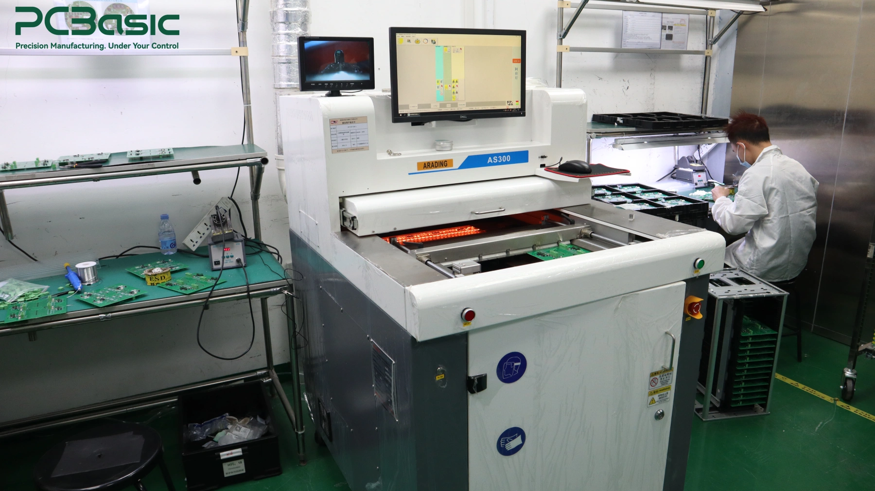
After a servo drive PCB assembly is soldered, it may seem fine upon inspection, but this does not mean it will definitely work properly once powered on. Many issues will only become apparent when the power is connected and the motor is attached. Therefore, it is best to conduct inspection and testing in stages. SPI, AOI, and X-Ray mainly check for "whether it is properly assembled and soldered", while electrical and functional testing are to confirm "whether this board can work normally in the power-on state".
These inspection methods each look at different things:
|
Method |
What It Can Check |
What It Cannot Prove by Itself |
|
SPI |
Solder paste volume, height, area, and offset |
Final joint quality or electrical function |
|
AOI |
Missing parts, polarity, placement shift, visible solder defects |
Hidden joints or actual circuit behavior |
|
X-Ray |
Hidden joints, bridges, thermal-pad coverage, obvious voiding |
Whether the circuit works correctly under power |
For example, AOI can confirm whether components are missing, reversed, or shift, but it cannot show whether the current detection is accurate. X-Ray can see the solder conditions under a QFN, BGA, or power package, but it cannot prove that the power stage will definitely work normally when carrying a load. Therefore, these inspection methods are more like checking different types of manufacturing problems, rather than who can "handle everything".
After the visual and solder inspections are completed, full-power is generally not applied immediately. A more prudent approach is to conduct a basic electrical inspection first. Based on the design of the board and production volume, methods such as continuity testing, ICT, or flying probe testing can be used to identify shorts, opens, and selected circuit faults.
Next, a controlled power-on is carried out. Usually, the following checks are performed:
• Power rails and operating current
• Firmware programming
• Communication interfaces
• Encoder or resolver inputs
• Current and voltage sensing signals
• Gate drive, PWM, and protection functions
At the FCT stage, the focus is no longer just on "whether the circuit is connected or not", but on whether the servo motor controller board or servo motor driver board can perform the specified functions. For servo drive PCB assembly, staged power-on is particularly important. Because if there are hidden problems in the power stage itself, if the full operating voltage is applied directly from the start, it may damage the PCBA and even the test fixtures.
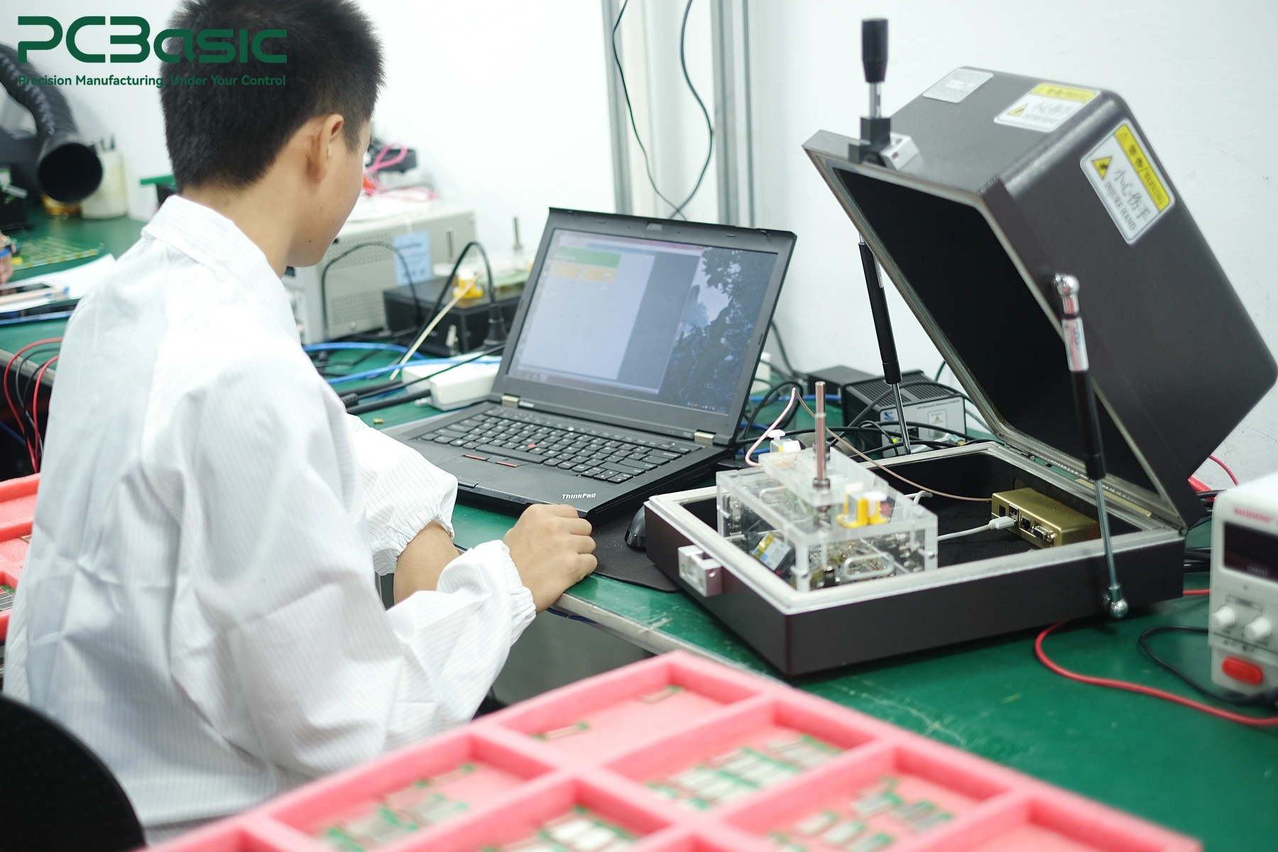
There are still some issues that cannot be detected at all during the low-power test. What happens then? At this point, you need to see the performance under actual load or simulated load. According to product requirements, load testing can help identify issues such as unstable current regulation, abnormal feedback, communication failures, or malfunctioning protection functions.
The thermal verification is the same. If the temperature of a certain power device is abnormally high, it may indeed be related to the welding or heat dissipation contact, but it may not necessarily be an assembly problem. PCB design, firmware, cooling conditions, motor status, and even the actual load can all affect the temperature rise.
Therefore, load testing and thermal testing cannot be directly applied with a fixed standard. The specific testing conditions and determination range need to be determined based on the actual motion control PCB assembly project and customer requirements.
The prototype can work, which is a good start. But this does not mean that mass production can also be consistently stable. Before truly entering mass production, we still need to confirm that the design data, BOM, firmware, testing methods and production parameters can be consistently executed, rather than relying on "just getting it right" once in a while.
Early servo driver PCB assembly not only needs to check the electrical functions, but also needs to ensure that this board can be smoothly mounted, soldered, programmed, tested and inspected.
Issues related to component orientation, solder quality, connector compatibility, test points, thermal performance and fixture requirements should be clarified as much as possible during the prototype or first article stage. After identifying problems, they should also be updated in the PCB, BOM, firmware or test specifications instead of leaving them to be solved through rework later.
If conditions permit, it is best to conduct another pilot build close to the conditions for formal mass production. Use the planned materials, stencil, reflow soldering settings, programming method and test plan to run through it once. This makes it easier to detect the real mass production risks in advance.

After entering the production stage, the key point becomes "whether each batch can be produced identically". The PCB and BOM versions, substitute materials, firmware, inspection results, repair records and functional test data should all be kept under control and traceable.
In this way, if any problems arise in the future, one can check specific material batches, process changes, firmware versions or test records instead of relying solely on experience to guess the reasons.
For servo drive PCB assembly, motor control PCB assembly and industrial automation PCB assembly, mass production is not simply making several more prototypes, but transforming each key process into a repeatable and traceable procedure.
In PCBasic, prototyping and mass production can be connected through first-article validation, a MES-based traceability system, SPI, AOI, X-Ray, and functional testing. This ensures that during the transition of the servo drive PCB project from early pilot production to repetitive production, the material version, process records, inspection results, and test data can all remain associated and traceable.
Reliable servo driver PCB assembly cannot be achieved merely through a single process or a specific inspection method. The real challenge lies in integrating power devices, control circuits, feedback interfaces, mixed SMT and THT assembly, as well as test requirements within a controlled manufacturing process.
Even a circuit board that appears normal in appearance after assembly may still reveal problems when powered on or under load operation. Therefore, inspection, electrical testing, functional verification, and traceability are just as important as the placement and soldering themselves. For servo drive PCB assembly, the goal is not merely to produce a working prototype, but to transform this prototype into a production process that can be consistently and stably repeated across different batches.
For PCBasic, the goal is not merely to produce a servo drive board that "works this time", but to assist the project in moving from the prototype stage to mass production and maintaining stable and repeatable assembly and testing results throughout the process.
Q1: What is a servo driver PCB?
A servo driver board converts motion-control commands into controlled power for a servo motor while processing feedback such as position, speed, or current. Some designs combine all functions on one PCB, while others use separate servo drive control board and servo drive power board assemblies.
Q2: How is a servo drive PCB assembly tested?
A servo drive PCB assembly may use SPI, AOI, X-Ray, ICT or flying probe, electrical testing, firmware programming, and FCT. Depending on the project, load, feedback, communication, and thermal tests may also be required.
Q3: What should be checked before moving a servo driver PCB into mass production?
Before volume production, confirm the PCB and BOM revisions, firmware, assembly files, test requirements, approved components, and traceability plan. These items should remain controlled from prototype through production.
Assembly Enquiry
Instant Quote
Phone contact

+86-755-27218592
In addition, we've prepared a Help Center. We recommend checking it before reaching out, as your question and its answer may already be clearly explained there.
Wechat Support

In addition, we've prepared a Help Center. We recommend checking it before reaching out, as your question and its answer may already be clearly explained there.
WhatsApp Support

In addition, we've prepared a Help Center. We recommend checking it before reaching out, as your question and its answer may already be clearly explained there.
