
Global high-mix volume high-speed PCBA manufacturer
9:00 -18:00, Mon. - Fri. (GMT+8)
9:00 -12:00, Sat. (GMT+8)
(Except Chinese public holidays)





HomePage > Blog > Knowledge Base > Motor Control PCB Assembly: Manufacturing, Testing, and Reliability Challenges
Table of Contents
1. What Makes a Motor Control PCB Different?
2. Why Motor Control PCB Assembly Is More Demanding
3. Preparing a Motor Control PCB for Reliable Manufacturing
4. Motor Control PCB Assembly Process
5. Inspection and Testing of Motor Control PCB Assemblies
6. Matching the Assembly Strategy to the Application
A stuttering robotic arm during
movement. An electric bike control system that does not work due to overheating
while climbing an incline. A conveyor motor that causes an overcurrent fault,
even when there’s nothing wrong with it. All of these situations can be related
to problems in the motor control PCB assembly, rather than some flaw in the
motor itself.
Motors use electric energy to perform mechanical work within almost any industry sector – from automated production facilities to electric vehicles – and modern motor-control systems rely on electronics that must handle repeated current switching. Motor control PCB assembly can face electrical and thermal stresses that a typical low-power logic board may not, which creates distinct manufacturing challenges.
Industry analysis of the electric motor and drives market has repeatedly indicated the growth prospects that lie ahead in the coming years. This is due to the automation trends, energy-efficiency policies, and electric mobility that will increase demand for reliable motor-control electronics. All these require a control board that has the ability to perform its function under their special electrical and environmental conditions.
This article will guide you on how a motor control PCB differs from other electronic components, reasons why making one is difficult, and the processes used to assemble and test it.
A motor control PCB is not just an intermediary between two chips; depending on the application, it must detect motor position or current, do some processing, and drive a power stage that switches current. Some switching and control events occur on microsecond timescales.
Most motor controller circuit boards include four regions on a single circuit board: the control logic, which may be realized by a microcontroller or a DSP; the switching region, which includes a gate driver and power stage; a feedback region, which contains a current or position sensor; and protection circuitry for overcurrent and overvoltage events.
It is precisely the task of maintaining appropriate electrical separation and clean signal paths between these regions while placing them on a single motor control circuit board that makes the design of motor control PCBs challenging.
A design that positions the noisy switching region near the delicate current-sense trace may work under light bench conditions but malfunction or become unstable once the motor starts spinning under load.
The two are sometimes used interchangeably, but for practical purposes, a motor driver PCB usually refers primarily to the power-switching stage, while a motor control PCB may also include control logic, sensing, feedback, communication, and protection. A closed-loop motor control system uses feedback to adapt its behavior to changing operating conditions.
Some applications do require only a basic motor driver PCB. Examples include a fan that works at a fixed speed and does not necessarily require any kind of feedback. There are, however, some applications that require the entire feedback system.
General electronics assembly rarely has to handle the combination of stresses that a motor controller board faces every day.
Some high-current motor control PCB runs tens or even hundreds of amps through traces and connectors depending on the application, which have to remain cool when carrying their rated load. The calculation of trace width, copper weight, and vias becomes necessary rather than an option because any underdimensioned copper starts acting as a heat generator the moment the current is drawn.
A board identical to a less powerful one in the schematic may act totally differently upon carrying real current because of the necessity of current-carrying capability verification.

Power components such as MOSFETs and drivers produce heat which needs to be removed from the board very quickly. Heat is removed by the means of thermal vias, copper pours, and in some cases a metal substrate, while solder joints of power devices should be strong enough to withstand thermal cycling without cracking.
A motor control PCBA which does not go through this process will silently deteriorate, thermal cycle after thermal cycle, until one joint cracks. At that point, it would be difficult to distinguish between a random field return and a design defect.
The fast switching edges in the power section emit electrical noise which may affect the current measurement through the current sensor or the encoder input signal. The correct placement ensures that the switching paths and the analog sensing paths are kept separate and the gate drive paths are as short as possible.
This would not be apparent when doing a bench test under a light load, but will only become clear when the motor actually starts rotating with a torque load.
Before a single component reaches a pick-and-place machine, a set of design and review decisions determines how smoothly motor control PCB manufacturing will go.
Some stack-up considerations for motor controller PCB manufacturing may include heavy copper layer use on the power plane, and separate planes for gate drive return planes. The number of layers used and copper thickness should be based on electrical, thermal, mechanical, and isolation requirements that the board will draw in service, not in bench test conditions.
For a review of the bill of materials of a motor control board assembly, any component that has a marginally low current and/or voltage capability relative to the application should be identified. Gate drives, MOSFETS, and current sensing resistors must all have sufficient margin to handle transient spikes.
Testing points on gate signals, current sensing, and important voltage buses save an incredible amount of time at bring-up and manufacturing tests. A design without these points necessitates probing the fine pitch contacts directly, which makes testing each unit coming off the assembly line extremely slow.
The standard assembly processes for PCBs remain relevant, although each stage has additional importance considering the fact that the board being assembled is a motor controller, and ignoring this fact is how a general process loses its importance in this particular case.
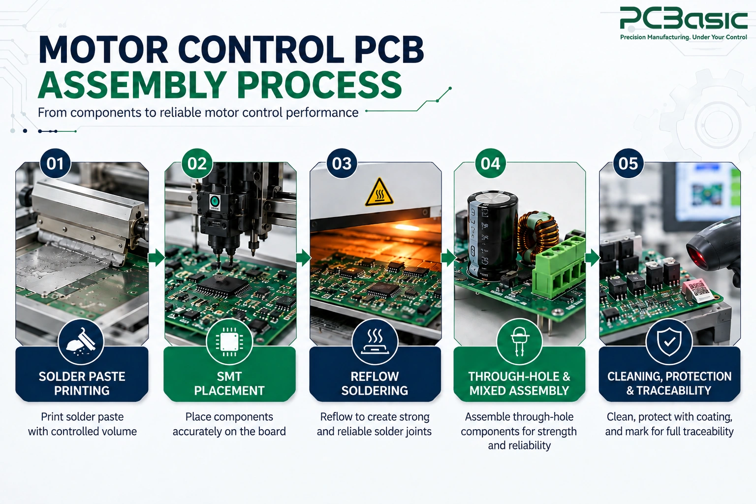
Solder paste volume is particularly important for a motor control PCB assembly when power MOSFETs use exposed thermal pads, because these pads require adequate solder coverage for effective heat conduction. If this is not properly controlled during stencil design and reflow, excessive voiding can occur, reducing heat transfer and potentially creating localized hot spots beneath the device.
Some high-current connectors, large capacitors, and inductors may use through-hole mounting and not surface mounting because these components have to withstand mechanical stresses which the surface-mount pads alone cannot bear. For mixed-technology motor controller PCB assembly, there is a reflow and wave or selective soldering process sequence which will protect heat-sensitive components mounted on the PCB.
Flux residue in proximity to high-voltage traces acts as a leakage path when humidity comes into the picture, making cleaning more important in this case compared to that for a low-voltage logic board. Conformal coating is applied in many motor control board assembly projects for moisture and dust protection.
A batch code and component lot code are just as important, as tracing the field failure needs to happen right down to the production batch and component lot.
Motor control PCBA testing must include much more than simple continuity because a board that tests fine with respect to basic electrical properties may very well fail when put into actual use.
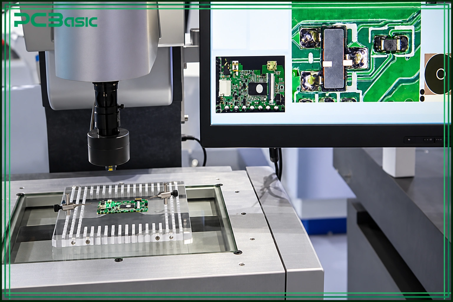
Solder paste inspection helps to detect paste quantity issues prior to reflow, and automated optical inspection detects misaligned or missing components commonly after reflow. X-ray inspection plays a significant role when it comes to power components featuring hidden thermal pads, since visual inspection cannot verify that the solder joint is sound.
In-circuit testing can detect opens, shorts, incorrect component values, and other assembly faults in gate drive and current sensing circuitry before firmware is loaded. Motor controller PCB testing at this point can identify wiring and component issues before attempting to spin the motor.
Moreover, motor controller PCB testing is not limited to detecting continuity issues. During powered or functional testing, technicians can verify that protection thresholds trip when they should, because proper protection behavior is essential to the circuit.
PCBA functional testing should be performed using the board with a real motor or a realistic load in the form of an electronic device that behaves like a motor, rather than relying on a resistive dummy load. PCB assembly for motor controllers should include checks for aspects such as current limitation, speed ramping, and behavior when stalled.
These are the conditions that differentiate between a good design and one that works on paper alone, and precisely the kind of conditions that would be missed by a generic functional test.
Motor controllers for small fans have completely different specifications than controllers for traction motors in electric vehicles; accordingly, the correct choice of assembly strategy will depend on these specifications.
When choosing a motor control PCB manufacturer, the OEM should make sure the company has experience with high-current PCB design and can support testability of the protection circuitry, not only SMT capability. The manufacturers who publish their process for power-stage PCBs usually notice the issues that generic PCB shops would never see.
PCBasic supports motor control PCB assembly projects with DFM review, thermal design considerations, and functional testing based on specific project requirements.

A motor control PCB assembly succeeds or fails long before the product reaches customers, based on the decisions that have been made about the copper weight, the thermal design, and testing months before.
Making the right decisions from the outset would save a lot of money compared to fixing problems later. If you are looking for a manufacturing partner who understands that motor control PCB assembly is a separate discipline, not just a standard PCBA assembly, PCBasic would love to talk to you.
Q1: What is a motor control PCB assembly?
It is an assembly of a printed circuit board that is designed to drive and control the operation of an electric motor on a single board.
Q2: Why does a motor control PCB assembly need more thermal design than a standard PCBA?
Components of power-on motor controller boards will generate heat when loaded; therefore, thermal vias, copper pours, and even some metal core substrates are needed to maintain the temperature of the components and solder joints at the rated limit.
Q3: What is the difference between a motor driver PCB and a motor control PCB?
A motor driver board will typically include only the switching stage, whereas a motor controller board will include additional circuitry required for closed-loop control.
Q4: How is testing different for a motor control PCBA compared to a typical board?
Testing must go further than simply verifying continuity; it must be able to verify real-life performance characteristics such as current limiting, speed control, and protective response while the motor is loaded.
Q5: What should an OEM look for in a motor control PCB manufacturer?
Look for experience in high-current design, heat dissipation, and functional testing under load because these have a direct effect on the way that the board will operate in its environment.

Assembly Enquiry
Instant Quote


Phone contact

+86-755-27218592
In addition, we've prepared a Help Center. We recommend checking it before reaching out, as your question and its answer may already be clearly explained there.
Wechat Support

In addition, we've prepared a Help Center. We recommend checking it before reaching out, as your question and its answer may already be clearly explained there.
WhatsApp Support

In addition, we've prepared a Help Center. We recommend checking it before reaching out, as your question and its answer may already be clearly explained there.
