
Global high-mix volume high-speed PCBA manufacturer
9:00 -18:00, Mon. - Fri. (GMT+8)
9:00 -12:00, Sat. (GMT+8)
(Except Chinese public holidays)





HomePage > Blog > Knowledge Base > Water Level Sensor PCB Assembly: Sensing Methods, Protection, and Testing
1. How Sensing Methods Affect Water Level Sensor PCB Assembly
2. What to Confirm Before Assembling the Sensor Board
3. Protecting the PCBA from Moisture Without Affecting Sensing
4. How Water Level Sensor PCB Assemblies Are Inspected and Tested
Therefore, for water level sensor PCB assembly, it is not enough by simply soldering the components in place. The solder joints must ensure stable electrical connections, and the sensing area must not be covered by residual flux or conformal coating. The coating blocks water vapor and may also accidentally seal the probe. These two issues need to be handled separately.
Before starting production, the buyer also needs to discuss with the factory on the test plan: what kind of water to use for testing, how many times to perform dry and wet cycles, whether the readings are stable when the pump is started and stopped, and whether a retest is needed after applying the coating. Let's start with the sensing method and explain how assembly, protection, and water level sensor testing are mutually restrictive.
The sensing method has been determined, and thus the procedures for assembly, protection, and testing become clear. The electrodes are immersed in water, measured through the tank wall, or connected to an external probe. The requirements for these three types of boards are different. It is best to clarify this before water level sensor PCB assembly starts.
|
Sensing method |
Assembly key points |
|
Conductive sensing |
Electrodes must not be covered by coatings, keep clean |
|
Capacitive water level sensing |
Position, gap, and coating thickness of electrodes should be consistent before and after |
|
External sensors (ultrasonic, pressure, float) |
Each item of mounting, wiring, and sealing should be checked separately |
The conductive sensing connects the two electrodes through water. The electrodes can be the traces on the water level sensor PCB, or independent probes. The electrical conductivity of water changes, so a board calibrated with tap water may not be accurate when placed in pure water. The materials and detection thresholds should be selected based on the actual water quality.
Capacitive water level sensing measures the change in capacitance. If designed properly, it can be measured through a non-conductive tank wall. However, if there is metal nearby, the wiring is incorrect, or the coating thickness changes, the reading will be inaccurate. Water level sensor board assembly should follow the approved installation requirements and materials. If it is modified, it should be recalibrated.
The board with a water pump or valve is the water level controller PCB. First, determine whether it directly cuts off the load or sends a signal to the external driver. The water level sensor testing not only checks if it can detect water, but also examines whether the reading will jump or trigger false alarms when the output of the water level sensor PCBA switches.
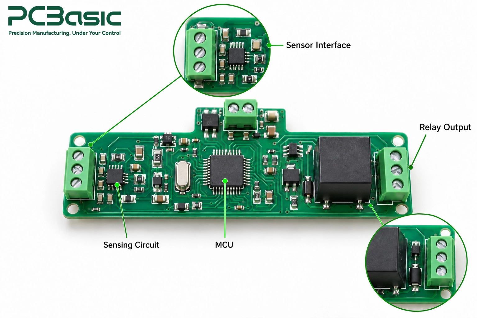
Before water level sensor PCB assembly begins, the factory needs clear production requirements. Lack of details may delay the assembly process or result in the omission of important inspection items in the testing plan.
• Files and firmware: Gerber, drilling files, the BOM, assembly data, and assembly drawings use the same version. Those to be programming, along with the firmware version and programming instructions, should be provided.
• Component replacement: Which components can be replaced and which ones require prior approval should be clearly stated in advance. Even if the package is the same, it does not mean that the sensing performance of the water level sensor PCBA is the same.
• Operating conditions: What liquid to measure, its temperature, whether it will get damp; supply voltage, range, output format, and allowable error range.
• Drawing Specifications: The PCB drawing of the water level sensor should indicate the electrode surface treatment, coating areas, and shielding boundaries. If the electrode needs to be in contact with water, it must be left un-covered.
• Mechanical and Process: Spaces should be reserved for the positions of fasteners, connectors, cables, and test probes. Special soldering, cleaning, and drying requirements should be included in the instructions for the water level sensor board assembly.
• Output and Testing: For water level controllers with built-in pumps, verify if the rated values are sufficient for the starting current and operating current. The calibration method, determination of limits, inspection items after coating, and the final determination should be agreed upon with the factory for the water level sensor testing.
These contents will be put into the approved production documents. Each board will be manufactured and inspected according to the same set of requirements, so that the water level sensor PCB assembly will not be the same for each batch.

Let's first consider where the board is placed and what it might encounter. The water level sensor PCBA installed above the water tank is concerned with condensation water and splashing water. The immersion probe needs to be able to remain submerged in the liquid for a long time, and the protection plan also needs to be verified through immersion tests. Conformal coating can prevent moisture, but not water immersion. Don't expect it to handle everything alone. The enclosure, seals, connectors, and cable entry points need to be selected together.
Before coating or filling, make sure the board is clean and dried. Even if contaminants are covered underneath, there will still be leakage and corrosion. Which areas should not be coated? Connector contacts, programming interfaces, and the marked prohibited coating areas must be covered. The conductive electrodes that will directly come into contact with water must be exposed.
Capacitive water level sensing is most likely to be biased by the coating. The protective material will change the baseline capacitance, and the sensitivity will also change. Engineers should first verify the material, thickness, and coating position clearly, and then the factory will follow the confirmed requirements for construction. Whether to leave an air gap in the sensing area depends on the specific design and cannot be generalized.
During water level sensor PCB assembly, pay attention to three things: whether the coating is applied properly, whether it is fully cured, and whether it has entered the prohibited coating area. After coating, filling, and installing the enclosure, conduct water level sensor testing according to the final configuration. Whether calibration is needed and when to calibrate should be written into the production requirements in advance.
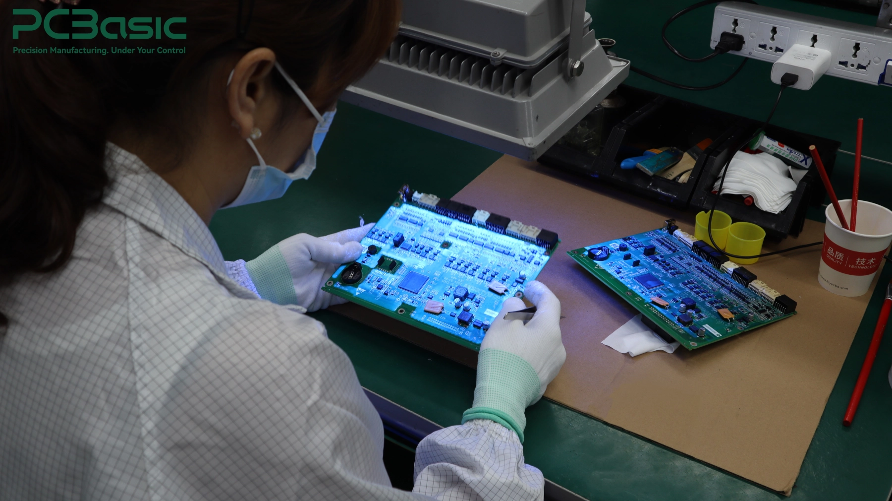
Before powering on the water level sensor PCBA, first inspect the appearance. For SPI, check how the solder paste is applied. AOI checks for visible defects in the mounting and solder joints. For the solder joints hidden beneath the components, use X-ray if necessary. For the three types of components - relays, connectors, and wiring terminal - in addition to checking the solder quality, also check the orientation and fixation. After powering on, use ICT or flying probe testing to test the connections and some component parameters.
The water level sensor testing follows the specifications item by item: power supply, current, sensing input, output. The fixture can simulate resistance, capacitance and sensor signals, but it cannot replace real water, tank, and installation conditions. The water level controller PCB also needs to check the switching threshold, hysteresis, alarm, relay action, and whether it can recover after an anomaly.

Capacitive water level sensing usually requires empty liquid level, full liquid level, or multi-point calibration. The extent of testing for each unit, the amount of sample extraction, should be determined in advance. The board revision, firmware version, calibration data, and test results cannot be missing at all.
PCBasic provides water level sensor PCB assembly services: component sourcing, SMT assembly, through-hole soldering, inspection, as well as the agreed functional testing. Our team arranges SPI, AOI or X-ray based on the packaging and solder joint structure. We will also evaluate the programming, fixtures, and test plans in combination with the firmware, sensing requirements and acceptance standards you provide. Production and test records are bound to the batch and can be retrieved later.
A water level sensor PCB that lights up does not necessarily mean it is an accurate measuring board. The difference between the two is determined long before the production of the first board by factors such as the liquid, installation conditions, and sensing method. Whether the board is used for the front-end circuit of a capacitive water level sensor or for the water level controller PCB that manages the water pump, assembly, coating, and testing of the water level sensor, all these steps must be done according to these decisions. The performance needs to be checked once the final protective setup is complete, not just on the bare board.

Therefore, water level sensor PCB assembly is best carried out according to a mutually confirmed scheme rather than being split into a stack of independent purchase orders. Determine the liquid, installation conditions, protective materials, and acceptance limits in advance, so that each water level sensor PCBA is inspected according to the same standard before leaving the production line.
Contact PCBasic with your BOM, PCB files, and test requirements for discussion on component procurement, assembly, protection, and the mutually agreed test scheme.
Q1: Can the entire water level sensor PCB be conformally coated?
Not always. Conductive electrodes need liquid contact, while connectors and other interfaces may require masking. A water level sensor PCB using capacitive sensing may tolerate coating, but the material and thickness must be validated.
Q2: Does every assembled board need testing in water?
Not necessarily. Routine water level sensor testing can use validated electrical simulation. Physical liquid-level tests are still needed to establish and verify performance with the intended sensor, tank, and liquid.
Q3: Is a water level controller PCB the same as a sensor board?
Not necessarily. A sensor board detects or processes level information. A water level controller PCB also uses that information to operate outputs, such as pump commands or alarms. One assembly may perform both functions.

Assembly Enquiry
Instant Quote



Phone contact

+86-755-27218592
In addition, we've prepared a Help Center. We recommend checking it before reaching out, as your question and its answer may already be clearly explained there.
Wechat Support

In addition, we've prepared a Help Center. We recommend checking it before reaching out, as your question and its answer may already be clearly explained there.
WhatsApp Support

In addition, we've prepared a Help Center. We recommend checking it before reaching out, as your question and its answer may already be clearly explained there.
