Global high-mix volume high-speed PCBA manufacturer
9:00 -18:00, Mon. - Fri. (GMT+8)
9:00 -12:00, Sat. (GMT+8)
(Except Chinese public holidays)
Global high-mix volume high-speed PCBA manufacturer
9:00 -18:00, Mon. - Fri. (GMT+8)
9:00 -12:00, Sat. (GMT+8)
(Except Chinese public holidays)
HomePage > Blog > Knowledge Base > Comprehensive Guide to Blank PCBs
Before any electronic product is truly put into use - whether it's a smartphone, an IoT device, an industrial controller or various wearable hardware - everything starts with a blank PCB. It is like the "foundation" of an electronic device, responsible for supporting all components and providing the necessary electrical pathways, allowing current and signals to flow as designed, thus enabling the entire system to function properly.
Many engineers and purchasers tend to focus on finished PCBs or PCBA with components already soldered. However, in fact, whether the product can operate stably, whether the subsequent assembly is smooth, or whether the reliability meets the standards are often determined at an earlier stage. What truly affects all of this is this seemingly simple blank printed circuit board.
If a blank PCB board itself has poor material quality, insufficient precision, or unstable lamination structure, problems may occur during subsequent surface mount technology (SMT) mounting, soldering, and even long-term use. On the contrary, high-quality substrates can ensure the soldering results, signal integrity, heat dissipation capacity and product lifespan from the source.
In this guide, it will help you understand the essence and basic composition of the blank circuit board from a more professional perspective, and why choosing reliable blank PCB boards will directly affect the performance of the final electronic product.
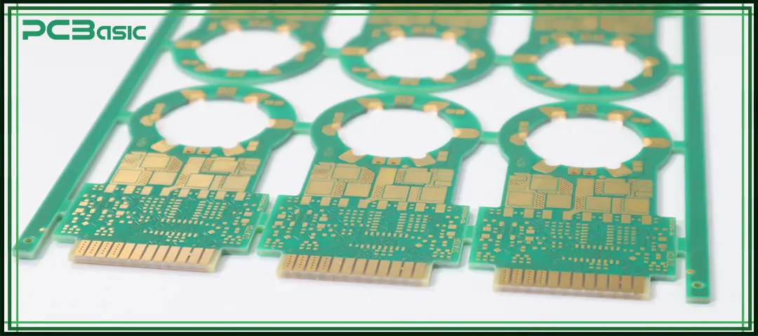
Blank PCB (printed circuit board) refers to a circuit board that has been processed with circuits, copper traces, pads and multilayer structures, but no electronic components have been soldered yet. We can understand it as the skeleton or base frame of an electronic product. All components, such as ICs, resistors, capacitors, connectors, and BGAs, will eventually be fixed and soldered onto this substrate, providing the basic framework for the entire subsequent electronic system.
To put it more straightforwardly, the blank circuit board is actually the underlying structure that determines whether an electronic device can work properly. It affects:
• Electrical connectivity: Whether signals and current can flow accurately according to the design.
• Mechanical structure: Whether components can be mounted securely and withstand vibration or physical impact.
• Impedance and signal behavior: Whether high-speed signals remain clean, stable, and free from interference.
• Heat dissipation: Whether heat generated during operation can be released effectively.
• Physical component layout: Whether component placement is logical, manufacturable, and easy to solder or maintain.
Before the SMT assembly or through-hole soldering begins, the first thing that engineers receive is a blank PCB board. After going through processes such as design, cutting, circuit imaging, drilling, and plating, these boards become fully processed blank boards that can be directly used for production. Engineers then use these blank boards for surface mount, soldering, and testing, ultimately completing the functional realization of the entire electronic product.
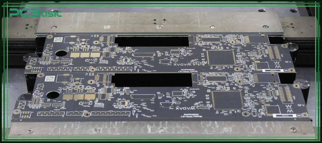
The material composition of a blank PCB board directly affects its electrical performance, heat dissipation capacity and mechanical strength. Different types of circuit boards use different materials, but the majority of blank printed circuit boards consist of the following parts.
This is the core material of the circuit board, providing the necessary rigidity and insulation performance for the PCB. Common substrates include:
• FR4 (fiberglass + epoxy resin) – most popular
• Polyimide – for flexible blank circuit boards
• Aluminum or copper – for metal core blank PCB boards
• PTFE/Rogers – high-frequency and RF applications
Copper foil is a key material for forming a circuit structure. It is usually laminated onto the surface of the substrate to serve as the foundation for creating traces, pads, and power/ground planes. A blank PCB may have copper on only one side, or it may have copper on both sides, or be built as a multilayer structure with dozens of layers.
The thickness and quality of the copper foil can affect the current-carrying capability, line impedance and overall signal integrity. Therefore, different specifications of copper foil are selected for different applications.
The solder mask is a protective coating covering the surface of the copper. It not only determines the color of the PCB, but more importantly, it protects the copper surface from oxidation and prevents solder from spreading during soldering, reducing defects such as solder bridges and shorts.
A good solder mask can also enhance the durability of the circuit board, keeping the circuit stable in environments with moisture, dirt, or elevated temperatures.
The silkscreen layer consists of the text, symbols and component markings on the surface of the PCB, which is used to help assembly technicians quickly locate components, identify orientation, and find test points.
Although silkscreen does not affect electrical performance, it is very crucial in assembly, debugging, and maintenance. Clear silkscreen markings effectively reduce the risk of assembly errors and improve engineering efficiency.
Surface finish is used to protect the exposed copper surface from oxidation and make subsequent soldering more reliable. Common finishes include HASL, lead-free HASL, ENIG, OSP, immersion silver, and immersion tin.
Different surface treatments vary in soldering quality, shelf life, cost and application scenarios. For instance, ENIG is more suitable for high-precision and high-reliability products, while OSP is often used in applications where cost performance is more sensitive.
After these materials are combined and processed together, they eventually form a blank circuit board that is ready for SMT assembly, through-hole soldering, and final functional testing.
Although no electronic components have been mounted on the blank PCB yet, it already contains many necessary structural and electrical features. These design elements will directly affect the subsequent assembly process, product performance and reliability. The following parts together form a PCB base that can be truly used for manufacturing and production.
Copper traces are the most crucial conductive part of a circuit board. They are responsible for connecting each component, ensuring that signals and currents can be smoothly transmitted within the system.
Pads are footholds where all components are fixed and soldered, and they are also one of the most crucial areas in electronic assembly. Whether it is SMT surface-mount components or through-hole components, they must rely on pads to be firmly mounted on the blank circuit board.
Vias are responsible for connecting signals and power between different layers of the circuit board. The through holes penetrate the entire board and are used for general connections. Blind holes connect the outer layer and the inner layer. The buried holes are hidden within the plate and are used in high-density multilayer structures.
Mounting holes are the key for the circuit board to be combined with the enclosure, standoffs, screws, or other structural components. They help the PCB maintain a stable position inside the product and prevent it from moving due to vibration or physical impact.
In high-power applications, thermal design is extremely crucial. Thermal relief structures and heat-dissipation areas can help blank PCB boards quickly dissipate heat during operation, avoiding reduced lifespan or failure of components due to high temperature.
Power and ground planes are very important structures in multilayer PCBs. They provide stable voltage references and low-impedance return paths for current. In high-speed or high-power applications, these layers can also reduce noise, minimize electromagnetic interference, and help the system maintain good signal integrity.
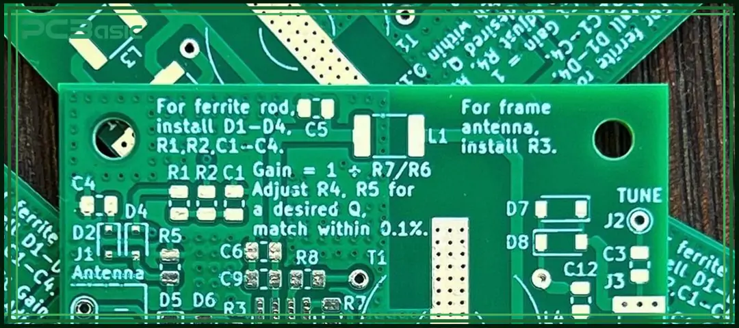
Different electronic products have different requirements for circuit boards, so different types of blank PCB boards need to be selected. The following are several of the most common types of blank PCBs.
|
Type |
Description |
Typical Materials |
Key Features |
Common Applications |
|
FR4 PCB |
The most widely used type of blank circuit board |
Fiberglass + epoxy resin (FR4) |
Good insulation, strong mechanical strength, high cost-performance, compatible with SMT/THT |
Consumer electronics, IoT devices, computers, and industrial electronics |
|
Metal Core PCB (MCPCB) |
A blank PCB board with a metal core layer |
Aluminum, copper |
Excellent heat dissipation, ideal for high-power designs, stable thermal performance |
High-power LED lighting, automotive electronics, power modules, motor drivers |
|
Flexible PCB (FPC) |
Bendable blank PCB boards made from flexible film |
Polyimide (PI) film |
Bendable, foldable, suitable for compact layouts |
Wearables, camera modules, smartphones, medical sensors |
|
Rigid-Flex PCB |
A hybrid blank circuit board combining rigid and flexible layers |
FR4 + Polyimide |
Offers both rigidity and flexibility, ideal for complex 3D structures |
High-end electronics, precision instruments, foldable mechanisms |

Time is money in your projects – and PCBasic gets it. PCBasic is a PCB assembly company that delivers fast, flawless results every time. Our comprehensive PCB assembly services include expert engineering support at every step, ensuring top quality in every board. As a leading PCB assembly manufacturer, we provide a one-stop solution that streamlines your supply chain. Partner with our advanced PCB prototype factory for quick turnarounds and superior results you can trust.
To manufacture high-quality blank printed circuit boards, the production process must be precise, stable and strictly controlled. The following are the standard manufacturing workflows commonly used in the PCB industry.
First, cut the large-sized copper-clad laminate sheets into the required production sizes. Subsequently, these sheets are then laminated under high temperature and pressure to firmly bond the copper foil to the substrate.
Next, evenly apply a layer of photoresist on the board surface, and then use an exposure machine to precisely transfer the circuit pattern onto the board surface. The developed pattern will determine the final trace shape of the blank PCB.
After the imaging is completed, the copper foil that is not protected by photoresist is removed through chemical etching, leaving only the required conductive traces.
High-speed mechanical drills or laser drills are used to create various holes on the PCB, including vias, through-holes, and mounting holes. These holes provide electrical connections between layers or mechanical support.
The drilled holes need to undergo copper plating to form reliable conductive pathways. Meanwhile, surface traces will also be plated to increase copper thickness, improving conductivity and enhancing durability.
After that, a layer of solder mask will be applied to the surface of the PCB. The coating can protect the copper surface from oxidation and prevent solder bridges or shorts during soldering, which is an important step to ensure assembly quality.
After solder mask curing, component labels, symbols, reference designators, and orientation marks will be printed on the surface of the PCB. These markings can help assembly technicians quickly locate and identify components, reduce error rates, and also facilitate later debugging and maintenance.
The exposed copper areas need to undergo surface finishing to prevent oxidation and ensure good solderability. Common finishes include ENIG, OSP, and HASL.
After fabrication, each blank PCB board will undergo open circuit/short circuit testing. The testing equipment will scan all conductive paths point by point to confirm that all paths are correct and error-free, ensuring that the circuit has no defects and can proceed to the subsequent processes normally.
Finally, the circuit board is routed, V-cut, or punched into its final shape according to the design. After forming, each PCB is inspected for dimensions, appearance, and structural integrity to confirm it meets all quality standards.
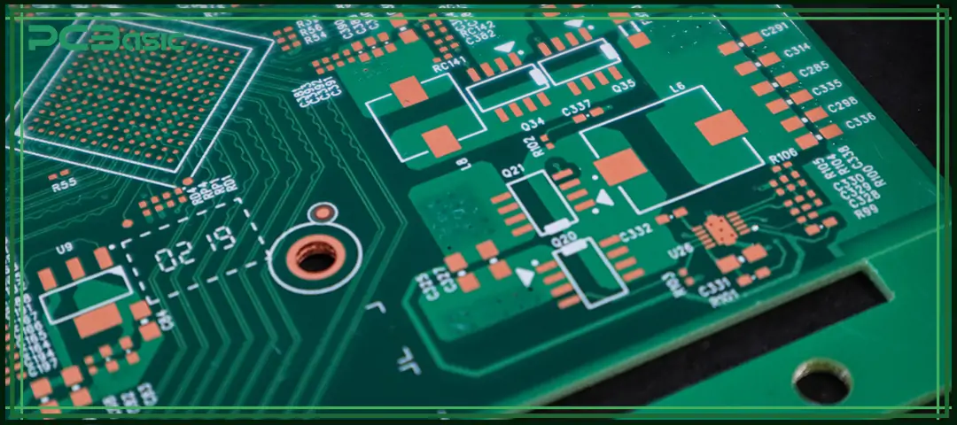
Since blank PCB boards are the basic structure of all electronic products, they exist in almost all kinds of electronic devices. The main application fields include
1. Consumer Electronics
Smartphones, routers, TVs, game consoles.
2. Industrial Electronics
PLC controllers, automation systems, sensors.
3. Automotive Electronics
ADAS, lighting, motor controllers, and infotainment.
4. Medical Devices
Patient monitors, imaging devices, wearables.
5. Aerospace and Defense
Avionics systems, communication modules.
6. IoT Products
Smart home devices, trackers, wireless modules.
7. LED Lighting
High-power LED engines using metal core blank PCB boards.
No matter which industry it belongs to, every electronic product ultimately originates from a blank circuit board. Through the processes of surface mount technology (SMT), soldering and assembly, it is gradually endowed with functions and becomes a complete electronic device.
Blank PCBs are the foundation of all modern electronic products. Whether it is an FR4 board, a metal substrate, a flexible board or a rigid-flex PCB, its quality and structure will directly affect the performance, reliability and manufacturability of electronic devices. Understanding the material composition and manufacturing process of blank PCB boards can help engineers and buyers make wiser choices and ensure that the products have advantages in both the design and production stages.
Choosing the right manufacturer, like PCBasic, for your blank printed circuit board is equally crucial. A precise, reliable and well-designed blank circuit board can not only improve the assembly quality of PCBA, but also enhance the product lifespan and overall stability, laying a solid foundation for the final electronic products.
1. What is a blank PCB?
A blank PCB is an unassembled circuit board containing copper traces, vias, and pads, but no components.
2. Are blank PCB boards the same as raw PCBs?
Yes. Blank PCB boards refer to raw, unpopulated PCBs before SMT or THT assembly.
3. What materials are used to make blank circuit boards?
FR4, polyimide, aluminum, copper, and special laminates like Rogers.
4. Can I order custom blank PCB boards?
Yes. Most manufacturers offer full customization of layers, materials, finishes, and thickness.
5. What industries use blank printed circuit boards?
All electronic sectors, including consumer, automotive, medical, industrial, and aerospace.

Assembly Enquiry
Instant Quote
Phone contact

+86-755-27218592
In addition, we've prepared a Help Center. We recommend checking it before reaching out, as your question and its answer may already be clearly explained there.
Wechat Support

In addition, we've prepared a Help Center. We recommend checking it before reaching out, as your question and its answer may already be clearly explained there.
WhatsApp Support

In addition, we've prepared a Help Center. We recommend checking it before reaching out, as your question and its answer may already be clearly explained there.
