Table of Contents
1.
Important PCB Assemblies a Robot Vacuum Cleaner Has
2.
Manufacturing Challenges in Robot Vacuum Cleaner PCB Assembly
3.
From Component Sourcing to Production Assembly
4.
PCB Functional Testing and Inspection Before System Integration
5.
How to Choose a Robot Vacuum PCBA Manufacturer
6.
Summary
7. FAQs
A robot vacuum is a compact mobile robot
designed to clean floors autonomously. So, it can map rooms, avoid chair legs,
climb thresholds, and get back to the dock. All of that requires electronics.
Demand keeps increasing. IDC states that in
2025, global smart vacuum unit shipments were 24.12 million, an increase of
17.1% from the year prior. Higher shipment volumes make consistent production
quality increasingly important.
Given the increase in shipments and
tightening targets, board manufacturers deserve a second look. This report
reviews the main boards, issues found in production, tests, and inspection to
help determine faults. If you are involved in the design, purchase, or supply
of these boards, you will be able to recognize faults that can lead to
complications and increased costs.
Important PCB Assemblies a Robot Vacuum Cleaner Has
Due to competition and the iterative nature
of the industry, the architecture of robot vacuums is consistently changing.
This has resulted in a wide range of configurations, but the main functions
stay the same.
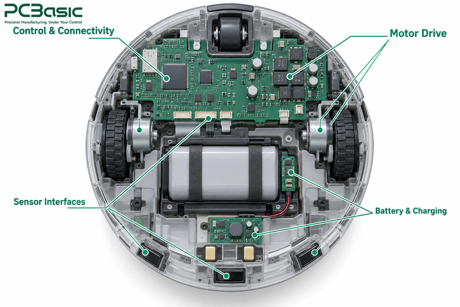
Control and Sensor Interface
Electronics
The control board can be referred to as the
"brain" of the robot vacuum. The control board can house memory and Wi-Fi
or Bluetooth modules. It can control navigation, clean on a schedule, and
interface with an external application.
Sensors supply this board with data
continuously. Depending on the model, inputs come from LiDAR, cameras,
gyroscopes, wheel encoders, cliff sensors, bump switches, and/or IR receivers.
Not all robots rely on LiDAR. Some models utilize gyro-stabilized or
camera-stabilized navigation.
This variety impacts assembly. Fine-pitch
processors, RF modules, and other components compete for limited space. One bad
joint near a sensor can create a software-like bug.
The design choices impact the assembly.
Shielding cans over RF sections and tall electrolytic capacitors also impact
assembly. Board-to-board connectors and their orientation also impact assembly.
When designers and assemblers come to an agreement on these details early,
first-article builds go a lot smoother.
Motor Drive, Power Management and
Charging Electronics
To move and clean, a robot vacuum relies on
several motors. A typical design utilizes two drive wheels, a fan to create
suction, a main brush, and side brushes. Design choices for motors can vary.
Each requires different driver circuits.
The power section of the board remains
equally as busy. A Battery Management System is utilized to protect Li-Ion
cells, monitor battery conditions, and, depending on the design, estimate the
remaining charge. A separate charging circuit may control charging. Next, DC-DC
converters step down the voltage for use in the control, sensor, and radio
circuits. Finally, charging contacts connect the robot to its dock for
charging.
Manufacturing Challenges in Robot Vacuum Cleaner PCB Assembly
Robot vacuum cleaner PCB assembly presents
significant challenges in designing, manufacturing, and assembling printed
circuit boards (PCBs). Costs must be kept as low as possible, and a small size
is generally preferred in the design of consumer electronic products.
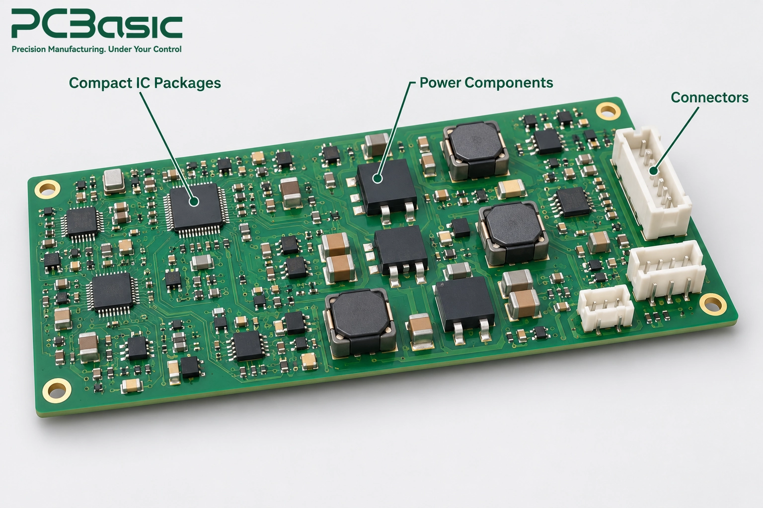
Compact Layouts and Mixed Component
Packages
Many robot vacuum cleaner PCBs contain compact
component packages (e.g., QFN and BGA) and power components with higher thermal
mass (such as power MOSFETs and motor driver ICs) in the same layout. Reflow
profiles for small component packages may not be adequate for higher-thermal-mass
components to achieve proper solder reflow and wetting.
There are also significant challenges in
designing and manufacturing stencils with the correct thickness and aperture
geometry for varying components in a given PCB layout. For example, too much
solder paste may bridge leads in fine-pitch components; on the other hand, too
little may leave insufficient solder between QFN terminals and PCB pads.
Warpage
Warpage of PCBs, due to factors such as
material properties, stackup imbalance, and thermal exposure, may introduce
significant stress at component solder joints, particularly those of BGAs.
Power Parts and Thermally Demanding
Solder Joints
A similar challenge is encountered in PCB assembly for the power circuitry
of a robot vacuum cleaner, in which high-current switching components (e.g., power
MOSFETs) and sensing (e.g., shunts) elements are mounted on the PCB. These
components need sufficient soldering to withstand repeated heating and cooling during
normal operation of the robot vacuum cleaner.
Pads connected to large areas of copper,
which draw heat away from the joints, may remain insufficiently wetted if they
do not reach the required soldering temperature. Thermal relief design, where
current-carrying requirements permit, and profile adjustment are used to
address these issues.
Certain rules don’t necessarily apply to all
boards. Things like copper weight, layer count, and voiding depend on design
considerations, current load, and the customer’s acceptance criteria. An excellent motor driver PCB assembly team
member verifies these during their own reviews instead of taking a wild guess.
Connectors, Mechanical Fit and
Selective Protection
Different types of connectors may need
selective or hand soldering. Precise mechanical fit with the housing is equally
important. A connector misaligned by half a millimeter may block final
assembly.
Some customers’ requirements may call for
conformal coating against humidity and/or dust. Others may require no coating.
Masking of connector mating surfaces, test points that require subsequent
access, and/or charging contacts is required where these areas must remain
uncoated. Resolving this is important prior to finalizing the production plan.
From Component Sourcing to Production Assembly
A great robot vacuum PCB assembly starts well
before the first PCB is produced. Delays during this process can be due to part
and data availability issues, as well as machine issues.
Components Sourcing, BOM Review, and
DFM
The first step is always a thorough review of
the BOM. Ambiguous or vague entries are flagged immediately.
Next is component
sourcing. Long lead times and/or allocation are common for MCUs, motor
drivers, wireless ICs and modules, and certain power ICs. Rigorous buyers
approve alternates and purchase from authorized or traceable channels.
There are other considerations, like the dry
storage and handling of moisture-sensitive components. Processors, BGAs, and
some sensors must be baked out prior to assembly when required by their
moisture exposure history and the manufacturer’s handling instructions. For a
robot vacuum cleaner PCBA which contains dozens of unique part numbers, the
disciplined sourcing and storage of components help improve first-pass yield
from day one.
There are simultaneous DFM checks. The team
examines pad designs and spacing, fiducials and panel layout, and access to
test points. Identifying a footprint error now can allow an early correction;
identifying the same error after a production run can require rework or a board
respin.

SMT Assembly, Through-Hole Assembly
and Firmware Programming
SMT assembly is
made up of three core steps: solder paste printing, pick-and-place, and reflow.
Each of these steps requires careful balance based on the package mix of the
board and the thermal mass of the components.
Through-hole parts are added next, along with
larger connectors and terminals. Power components may be soldered using wave or
selective soldering. Careful sequencing during mixed-technology boards helps
protect SMT components.
Firmware may be programmed into supported
devices before assembly, or in-circuit after soldering. Each board that
requires firmware must have the approved version and, if necessary, a unique
ID.
Prototype Approval and Repeatable
Batch Production
Important parts are finally brought together
in prototype
PCB assembly. A small first build gives the team valuable data on function,
fitting, and reflow profiles.
After prototype approval, the process is placed
under change control. Stencils, pick-and-place programs, and reflow profiles
are controlled. Repetitive batch production then follows the approved process,
with ongoing monitoring.
PCBasic supports the full path. We coordinate
the sourcing of components, SMT assembly, through-hole assembly, and firmware
loading under one plan. We also manage the transition from prototype PCB
assembly to production. Thus, the process you approved is the process used to
manufacture your production boards, with subsequent changes reviewed and
documented.
PCB Functional Testing and Inspection Before System Integration
In robot vacuum cleaners, final assembly is a
costly stage at which to find a bad PCB. Once the board is enclosed in the
housing, any defect on that PCB requiring board-level repair generally means
the housing must be opened. Inspection and functional testing of PCBs in robot
vacuum cleaner assemblies help reduce this risk.
SPI, AOI, and X-Ray Inspection
SPI is performed on printed circuit boards
after the stencil printing process to check the correct volume and position of
the solder paste. As paste-printing defects are generally less costly to
correct before component placement, this inspection can help reduce the overall
cost of the circuit board assembly.
Automated optical inspection (AOI) is
performed to check the assembly and component placement after the reflow
process. X-ray inspection is used to check hidden joints and voids in PCBAs.
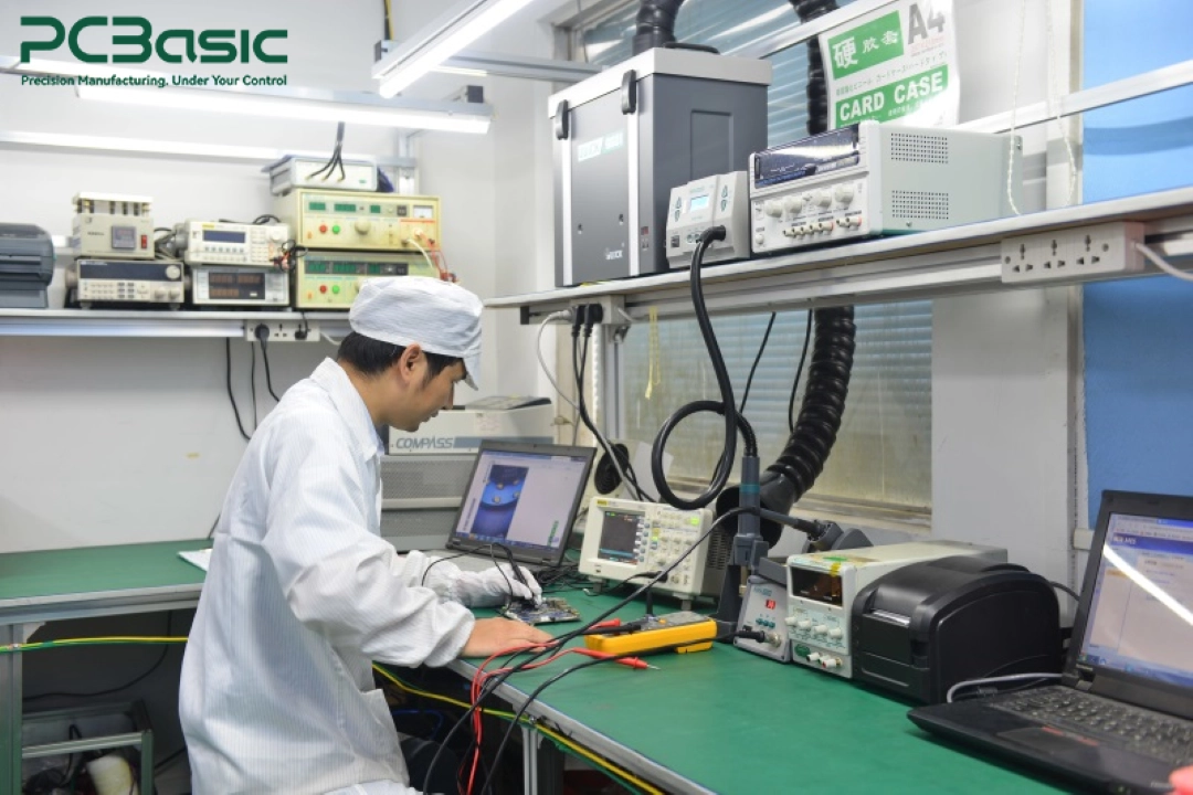
Electrical Tests and Firmware Loading
One step in verifying a circuit is to load it
with the approved firmware. Firmware loading alone only goes so far in ensuring
a functioning unit. Circuit boards must also undergo the specified powered
tests to verify their intended functions. Visual checks can only go so far to
ensure proper functioning of the circuit and its components.
Motor, Sensor and Charging Interface
Functional Testing
PCBA
functional testing simulates selected functions of the end product. A
specific fixture may be used with actual motors or simulated loads to test
motor outputs, read encoder feedback, and measure driver current under load.
Bump and cliff sensors can be triggered and tested for proper functionality
when included in the test setup.
Charging tests are equally important. The
board has to recognize the dock and start and stop charging within its
protection limits. Wireless modules have to be tested for a stable connection.
SPI, AOI, X-ray Inspection, Electrical
Testing, and Functional Testing are all part of our service offering at
PCBasic. For every Robot Vacuum PCB assembly project, we choose the right
service package for you, and if necessary, develop and perform functional tests
against your requirements.
How
to Choose a Robot Vacuum PCBA Manufacturer
Price is of course always important. However,
often the cheapest quote may include a narrower scope of inspection and/or test
support. The goal of a good robot vacuum PCBA manufacturer should be to reduce
your risk, not return it to you.
Evaluate Process Control and Test
Engineering Support
How do they ensure reflow profiles and
stencils are within specs? Do they use moisture-sensitive parts and control the
process accordingly? Are there traceability systems for both components and
finished boards? Specific, clear answers to these questions are good indicators
of a robust process control system.
Test engineering support says even more. Can
the supplier build fixtures? Can they convert your test specs into a repeatable
production test? A good manufacturer performs the test for you, not passes it
on.

Quote and Production Handoff
Requirements
Accurate quotes are based on complete data.
Provide Gerber or ODB++ data, the BOM showing approved alternates,
pick-and-place data, assembly drawings, firmware, and test data. Indicate the
target volumes and quality standards.
To remove unexpected issues and provide
production flexibility, guidelines are established for inspection levels, test
requirements, packaging, and procedures for ECO approvals. These factors impact
a quote and add value to a production plan.
PCBasic is well positioned as a turnkey PCB assembly and testing service provider. If
you are ready to move forward, provide us with your manufacturing data and test
requirements. Our engineers will assess your data and provide recommendations
for build, test, and production plans.
Summary
Developing a new robot vacuum or growing your
existing business? PCBasic is ready to partner with you from prototype PCB
assembly to full turnkey PCB assembly. Contact us for a free quote.
FAQs
Q1: What is involved in PCB assembly for a
robot vacuum?
This includes PCB assembly of the main
control, motor drivers, sensors, power management, charging, and other
circuits. This scope of work includes material procurement, PCB assembly (SMT
and THT), programming, inspection, and testing.
Q2: Do all robot vacuums have a different
PCB for each function?
No. PCB designs depend on cost, size, and the
approach of the brand. Some designs use many small PCBs, while others put most
functions on the main board.
Q3: What is the importance of PCBA
functional testing for a robot vacuum?
Not all functions can be tested during visual
inspection. For example, you cannot be sure that the sensors are working by
just looking at the PCB. The same goes for the charging and vacuum circuitry.
Functional tests help determine if the tested board functions operate in the
expected manner before it is sealed in the case. System-level tests are still
needed to verify navigation, docking, and cleaning performance. It helps reduce
the cost of rework.
Q4: How long does it take to assemble
prototype PCBs?
It varies. The lead time is determined by the
complexity of the board and the availability of the components on the board.
The procurement of long lead-time components often determines the schedule.
Q5: What kind of files do I need to
provide for a turnkey quote on a PCB assembly?
You will need PCB fabrication data (usually
Gerber files with drill data, or an ODB++ dataset). You will also need your
Bill of Materials (BOM), pick and place data, assembly drawings, and test
requirements. Schematics and firmware may also be needed for test development
and programming. Target quantity is helpful, too.