
Global high-mix volume high-speed PCBA manufacturer
9:00 -18:00, Mon. - Fri. (GMT+8)
9:00 -12:00, Sat. (GMT+8)
(Except Chinese public holidays)





HomePage > Blog > Knowledge Base > CCTV PCB Assembly: Manufacturing Processes, Testing, and Quality Requirements
1. What Makes CCTV PCB Assembly Different?
2. How a CCTV Camera Board Is Built
3. Testing and Common Manufacturing Mistakes
4. What to Ask Your CCTV PCB Assembly Manufacturer
CCTV PCB assembly involves assembling the electronic boards used to capture, process, record, or transmit surveillance video. Depending on the product architecture, these functions may share one board or be distributed across several connected assemblies.
The manufacturing requirements depend on the board’s role. A sensor board needs careful contamination control and positioning. A processing board may require attention to high-speed interfaces and heat dissipation. An outdoor camera adds enclosure, moisture, and surge-protection requirements.
|
Board Type |
Main Functions |
Manufacturing Priorities |
|
Image sensor board |
Captures image data and connects the sensor to processing electronics |
Sensor handling, surface cleanliness, placement accuracy, and package-specific soldering requirements |
|
IP camera processing board |
Processes video and supports Ethernet, Wi-Fi, or other interfaces |
Signal integrity, power stability, thermal management, and interface testing |
|
DVR/NVR mainboard |
Processes and records video streams and connects storage devices |
Processor and memory assembly, storage interfaces, cooling, and system testing |
|
Infrared illumination board |
Drives LEDs used for night vision |
LED polarity, solder quality, heat transfer, and illumination control |
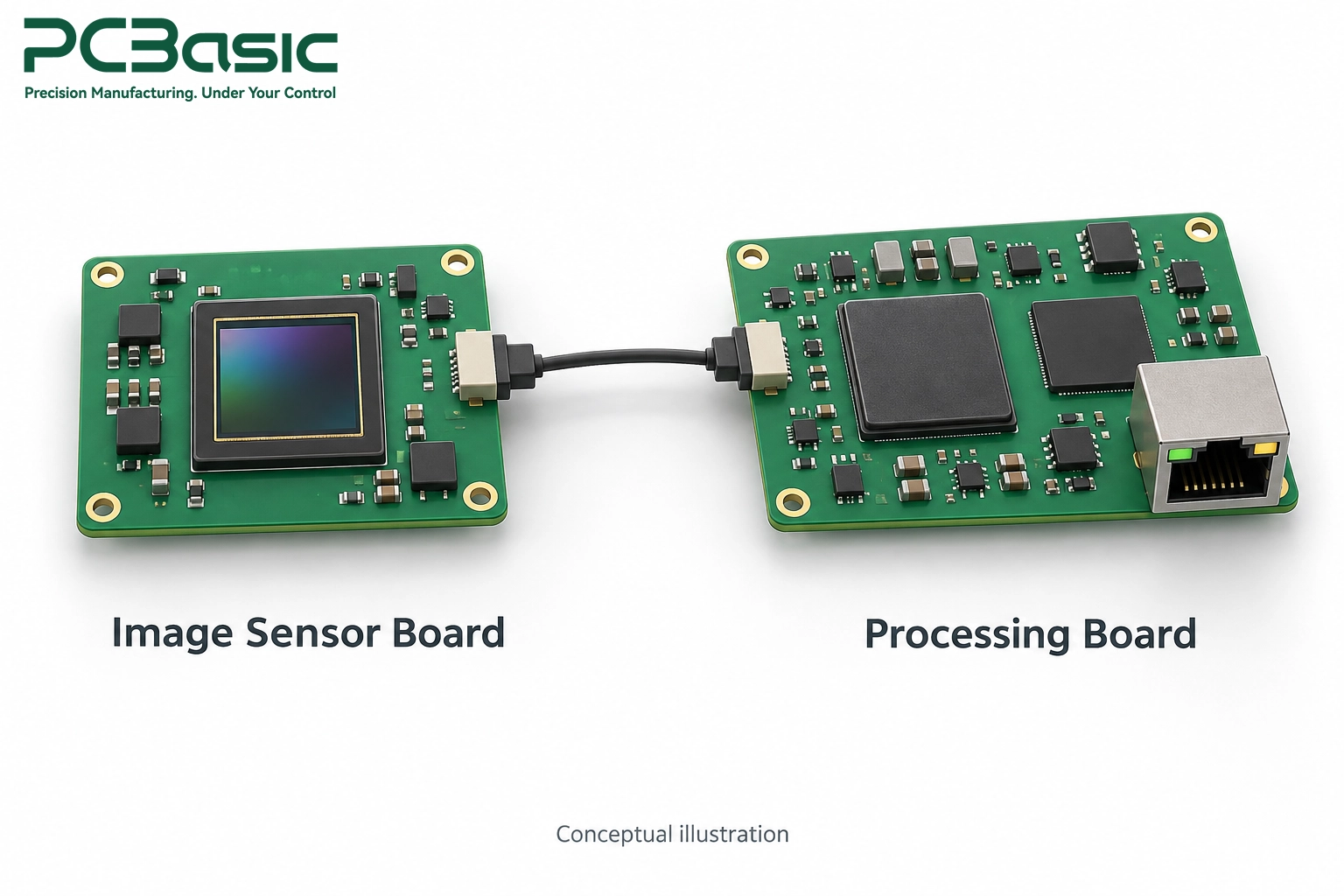
These requirements are not exclusive to CCTV products. What matters is how they interact within a compact camera or recording system.
Outdoor surveillance equipment may experience humidity, condensation, temperature cycling, and electrical transients. Protection should be selected according to the installation environment and product design.
Conformal coating can help protect exposed circuitry, but it does not replace enclosure sealing, board cleanliness, or moisture management. Coating materials and coverage also need to be compatible with connectors, optical surfaces, and subsequent repair.
Surge protection requires a coordinated design. Protective devices, grounding, interface layout, and enclosure connections should be evaluated together rather than treating a single TVS diode as a complete solution.
Interfaces such as MIPI, LVDS, Ethernet, and external memory buses have different routing requirements. Designers should follow the relevant device and interface guidance for impedance, length matching, reference planes, and discontinuities.
Manufacturing review should confirm that the specified stackup and controlled-impedance requirements can be produced consistently. Assembly inspection alone cannot establish whether the original routing is electrically suitable.
Sensor position, lens mounting, contamination, and mechanical tolerances affect image quality. A correctly soldered board may still produce an unacceptable image after optical assembly.
Heat also affects camera operation. The processor, power circuitry, and infrared LEDs should be assessed under representative operating conditions, including night mode and the intended enclosure.

Production begins with checking the BOM, board revision, component identities, and assembly instructions. For image sensors, the exact part number, package, orientation, and handling requirements deserve particular attention.
Moisture-sensitive components should be managed according to their supplier instructions and applicable handling requirements. Relevant records may include package opening times, floor-life exposure, dry storage, and any required baking.
Bare PCB storage and baking should be addressed separately using the board supplier’s guidance and the applicable process requirements. A component MSL rating should not be used as a universal baking instruction for bare boards. J-STD-033 addresses moisture-sensitive device handling rather than establishing one baking cycle for every assembly material.
Solder paste is printed through a stencil selected for the component mix and pad geometry. Solder paste inspection (SPI) can check deposit volume, alignment, and consistency before placement.
Pick-and-place equipment then positions the SMT components. Image sensors require handling methods suited to their package and optical surface. Pickup tooling, protective films, and cleaning methods should follow the sensor manufacturer’s instructions.
Contamination control matters throughout this stage. Particles, scratches, or unsuitable cleaning chemicals can damage optical surfaces or create visible image defects. Sensor manufacturers publish handling guidance covering these risks.
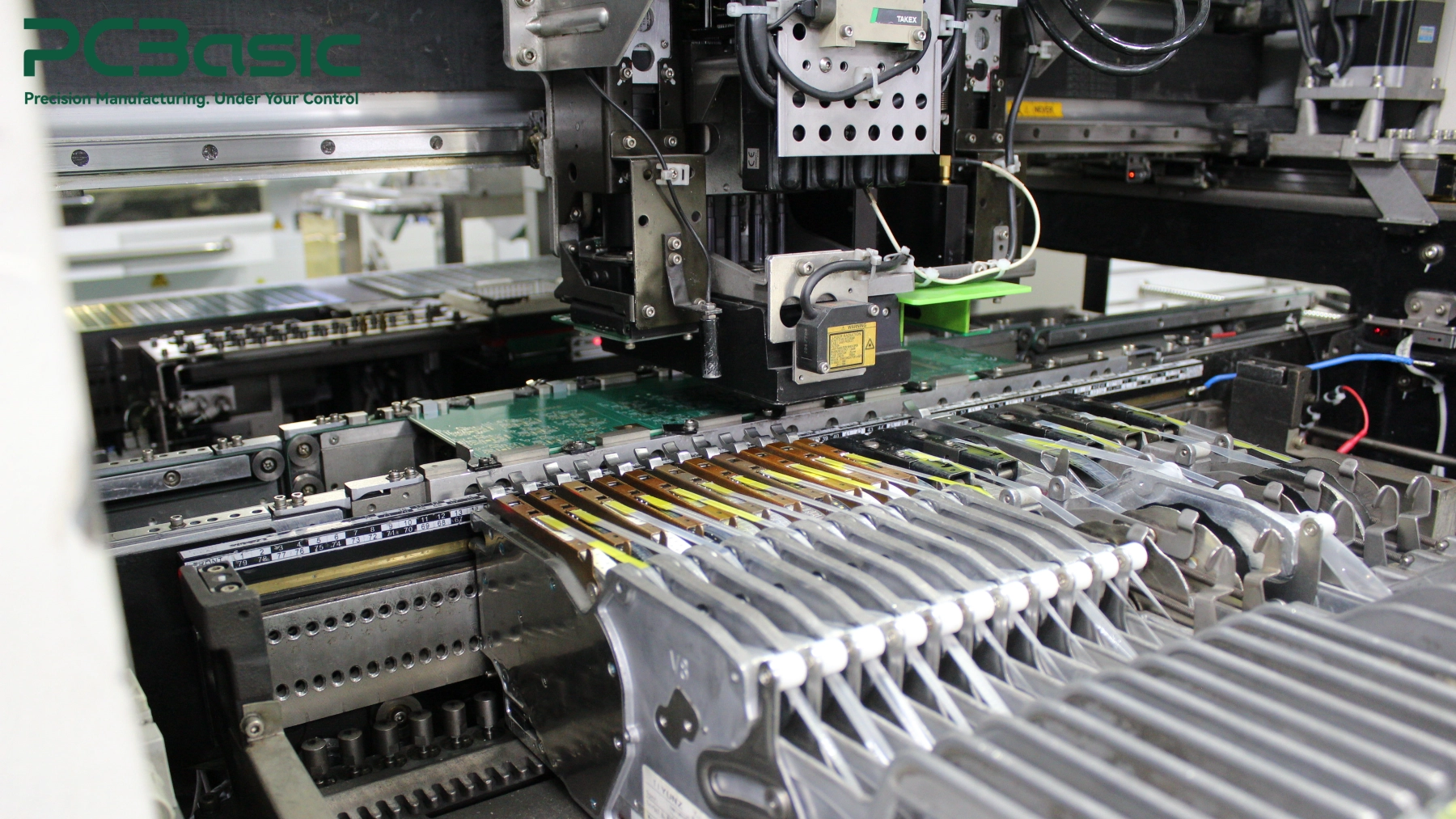
The reflow profile should suit the solder paste, board construction, and component temperature limits. Temperature measurements on a representative assembly help establish whether critical locations remain within the approved process window.
After reflow, automated optical inspection (AOI) checks visible assembly features such as component presence, orientation, and accessible solder joints. Hidden connections may require X-ray inspection, depending on the package and inspection plan.
Inspection methods should be selected around likely defects. AOI and X-ray provide different information, and neither replaces functional testing.
Through-hole connectors, cables, and other mechanical parts are assembled using a suitable soldering process. Heavy components may also need mechanical support.
Where conformal coating is specified, the process should define:
The order of coating, optical assembly, and testing should be agreed before production. This helps prevent contamination and avoids making later adjustments inaccessible.
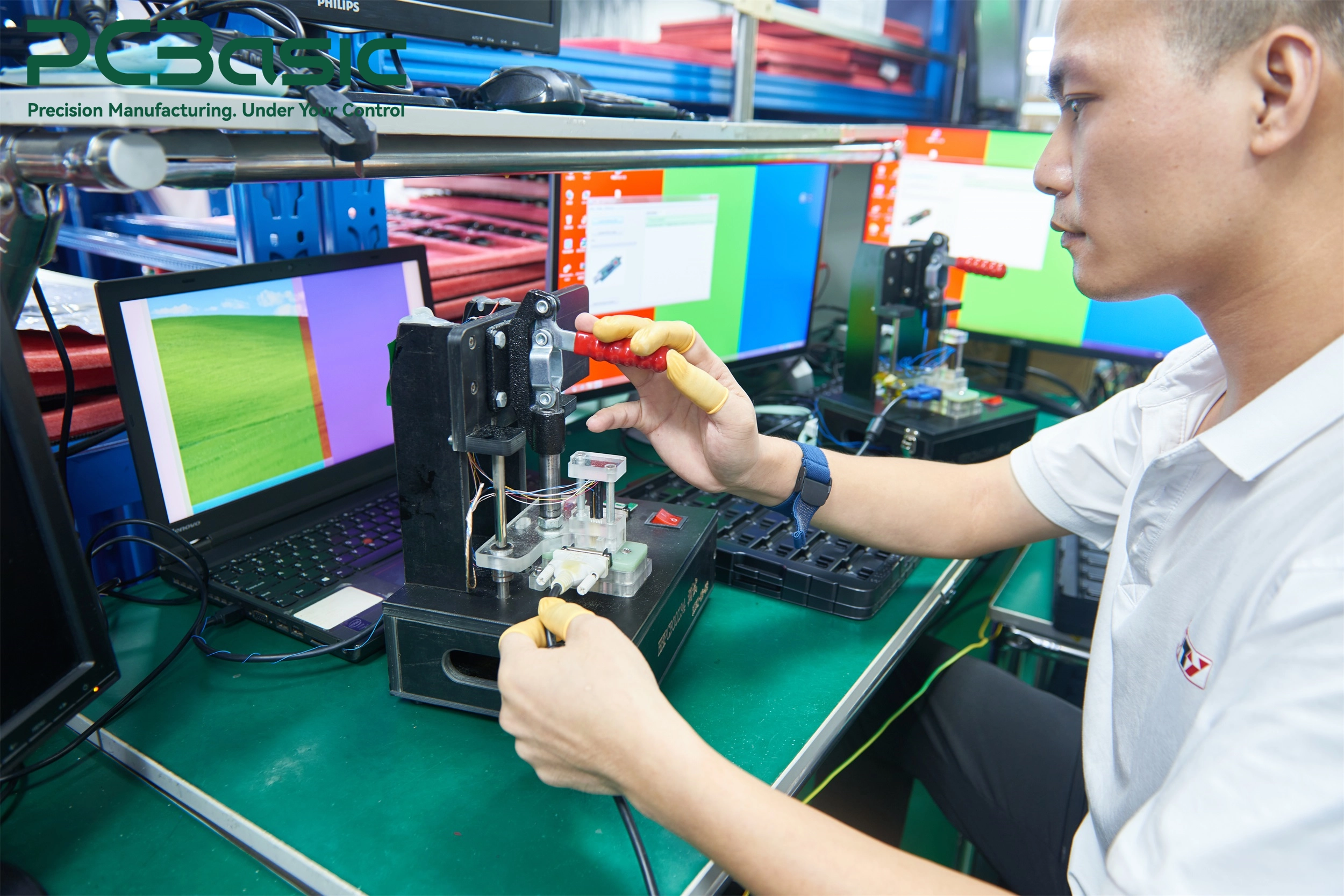
Electrical testing checks whether the board operates as intended. Depending on the design, the test plan may include power rails, current consumption, programming, communication interfaces, and video output.
Image evaluation checks the completed camera’s optical performance. Possible checks include focus, image uniformity, contamination artifacts, and day/night operation. The required conditions and acceptance limits should be defined by the product team.
Active optical alignment may be appropriate where the optical tolerances and manufacturing approach require it. Other products may use fixed mechanical alignment or a controlled focus-adjustment process. Dedicated alignment equipment should therefore be evaluated against the product requirements rather than treated as mandatory for every CCTV assembly.
A 4K camera does not automatically require HDI construction or a fixed layer count. The decision depends on package pitch, routing density, interface requirements, power distribution, and available board area.
Before specifying HDI, review whether a conventional multilayer stackup can meet the design requirements. If it can, HDI may add cost without solving a necessary routing problem. If it cannot, forcing the design onto a simpler stackup can create manufacturing or electrical compromises.
Solder mask color should not be presented as a general way to improve camera imaging.
Where a board sits near illumination components or within an optical cavity, surface reflectivity may affect the result. Its effect depends on geometry, wavelength, shielding, and the optical path. Any claimed benefit should be verified in the actual assembly.
An enclosure ingress rating does not answer every question about internal moisture. Assembly humidity, seal condition, temperature changes, and installation conditions still need consideration.
Coating, venting, sealing, and drying measures should be selected as part of the complete product design. Neither conformal coating nor a vent membrane should be prescribed as a universal requirement without assessing the application.
A camera that operates correctly on an open bench may behave differently inside its enclosure.
Thermal evaluation should include representative processor activity, ambient conditions, and infrared illumination where fitted. Check both sustained operation and transitions between operating modes. Low-light specifications alone do not establish acceptable thermal performance.
ISO 9001 certification and IPC Class 3 acceptance address different aspects of quality. A factory’s management-system certification does not, by itself, demonstrate that a particular assembly meets the agreed product acceptance criteria.
IPC-A-610 addresses electronic assembly acceptability, while J-STD-001 covers requirements for soldered assemblies, including materials and processes. Procurement documents should identify the applicable standards, revisions, classes, and customer-specific requirements.
Avoid treating Class 3 as a blanket promise of field reliability. The product still needs an appropriate design, validated processes, and testing for its operating environment. Cross-section reports should be requested when required by the relevant specification or qualification plan, rather than used as the sole proof of assembly compliance.

A useful supplier review connects each product requirement with a process control and an acceptance record.
|
Review Area |
Question to Ask |
Evidence to Review |
|
Sensor handling |
How are optical surfaces protected during storage, placement, and assembly? |
Handling instructions, tooling details, and contamination controls |
|
Moisture management |
How are sensitive components and bare boards managed? |
Exposure records, storage controls, and applicable baking instructions |
|
SMT process |
How are paste printing, placement, and reflow controlled? |
SPI results, representative thermal profiles, and inspection records |
|
Hidden solder joints |
Which packages require inspection beyond AOI? |
Package-specific inspection plan and X-ray records where specified |
|
Optical assembly |
How are focus and alignment controlled? |
Fixture procedures, test conditions, and acceptance limits |
|
Environmental protection |
How are coating coverage and excluded areas defined? |
Coating drawings, process specifications, and inspection results |
|
Functional testing |
What faults can the production test detect? |
Test coverage, limits, software versions, and recorded results |
|
Quality requirements |
Which standards, revisions, and acceptance classes apply? |
Agreed specifications, inspection criteria, and traceable records |
For a project with PCBasic, use this checklist to agree on assembly, inspection, coating, and test requirements during quotation and engineering review. If optical alignment or camera-level testing is required, confirm its scope and responsibility explicitly.
The handoff should also identify which items the customer supplies, such as firmware, test software, optical targets, fixtures, and reference samples. Clear ownership helps prevent a completed PCBA from reaching final integration without a workable acceptance test.
CCTV PCB assembly requires coordinated control of soldering, sensor handling, thermal performance, and environmental protection. Electrical testing confirms board operation, while image evaluation checks whether the completed camera meets its optical requirements.
Before production, define the inspection methods, test conditions, acceptance criteria, and responsibilities for optical integration. For projects with PCBasic, include these requirements in the engineering review so the assembly and test scope is clear before the first build.
Q1: Do 4K cameras require HDI PCBs?
No. Resolution alone does not determine PCB construction. Package density, routing space, signal requirements, and board dimensions determine whether HDI is needed.
Q2: Can a board pass electrical testing but still produce a poor image?
Yes. Electrical operation does not establish correct focus, alignment, or optical cleanliness. Include image evaluation at the appropriate stage of camera assembly.
Q3: Does every CCTV board need conformal coating?
No. The decision depends on environmental exposure, enclosure design, reliability requirements, and material compatibility. Coating should be specified where justified by the application.
q4: How should buyers verify a Class 3 requirement?
Agree on the applicable standards, revisions, acceptance class, and additional requirements before production. Review the relevant process and inspection records against that agreement rather than relying on a general supplier claim.

Assembly Enquiry
Instant Quote


Phone contact

+86-755-27218592
In addition, we've prepared a Help Center. We recommend checking it before reaching out, as your question and its answer may already be clearly explained there.
Wechat Support

In addition, we've prepared a Help Center. We recommend checking it before reaching out, as your question and its answer may already be clearly explained there.
WhatsApp Support

In addition, we've prepared a Help Center. We recommend checking it before reaching out, as your question and its answer may already be clearly explained there.
