
Global high-mix volume high-speed PCBA manufacturer
9:00 -18:00, Mon. - Fri. (GMT+8)
9:00 -12:00, Sat. (GMT+8)
(Except Chinese public holidays)





HomePage > Blog > Knowledge Base > How to Choose a Medical Device PCB Assembly Partner
1. Your PCBA Vendor Is Part of Your Compliance Chain
2. 5 Supplier Capabilities to Verify
3. Evaluate Total Cost and Engage Engineering Early
4. A 5-Step Evaluation Checklist for Procurement Teams
5. How PCBasic Meets These Requirements
Your assembly partner directly supplies the validation records and traceability logs that populate your Design History File (DHF). While a standard commercial Electronics Manufacturing Services (EMS) provider operating under ISO 9001 focuses primarily on throughput and unit price, a medical-grade PCBA partner builds process validation, risk management, and regulatory documentation directly into every production run.
This guide targets hardware engineering leads, procurement managers, and founders developing Class I, II, or III medical devices—especially teams moving through design transfer where production decisions directly impact regulatory filings.
ISO 13485 mandates formal risk management, process validation, and document control throughout the product lifecycle. Audited change-control procedures help reduce the risk of unauthorized component substitutions that can lead to field failures.
Regulations mandate that contract manufacturers of finished medical devices register with the FDA under 21 CFR 807, yet requirements vary regarding component and sub-assembly suppliers. Sub-assembly suppliers do not always require direct registration when the OEM holds the final 510(k) or PMA submission. However, Class III device components benefit from an FDA-registered supplier, whereas Class I or standalone Class II sub-assemblies function effectively under an audited ISO 13485 framework.
• Myth vs. Reality: Having an ISO 13485 certified partner does not guarantee direct FDA approval. ISO 13485 validates a supplier's internal quality management system, whereas FDA 510(k) or PMA clearances evaluate the safety and effectiveness of your complete medical device. You remain responsible for integrating your supplier's manufacturing records into your DHF.
• Verification Action: Request a copy of the ISO 13485 certificate and examine its exact scope statement. Ensure it explicitly covers contract manufacturing of medical device printed circuit board assemblies rather than general assembly or non-medical electronic lines.
Class 3 requirements establish strict criteria for solder joint fill, barrel penetration, and component alignment required for life-support, implantable, or high-reliability diagnostic hardware. Adhering to Class 3 reduces the likelihood of micro-cracks and cold solder joints under stress.
• Myth vs. Reality: Medical devices do not require full Mil-Spec components for high reliability. Neither IPC-A-610 Class 3 nor IEC 60601 mandates military-grade components. Medical designs rely on risk assessments, appropriate component derating, and environment-specific stress testing. Commercial or industrial-grade components operating well within design margins pass regulatory scrutiny when supported by test data.
• Verification Action: Request recent third-party IPC inspection reports and verify that certified IPC Trainers (CIT) or Application Specialists (CIS) remain active on the assembly line.
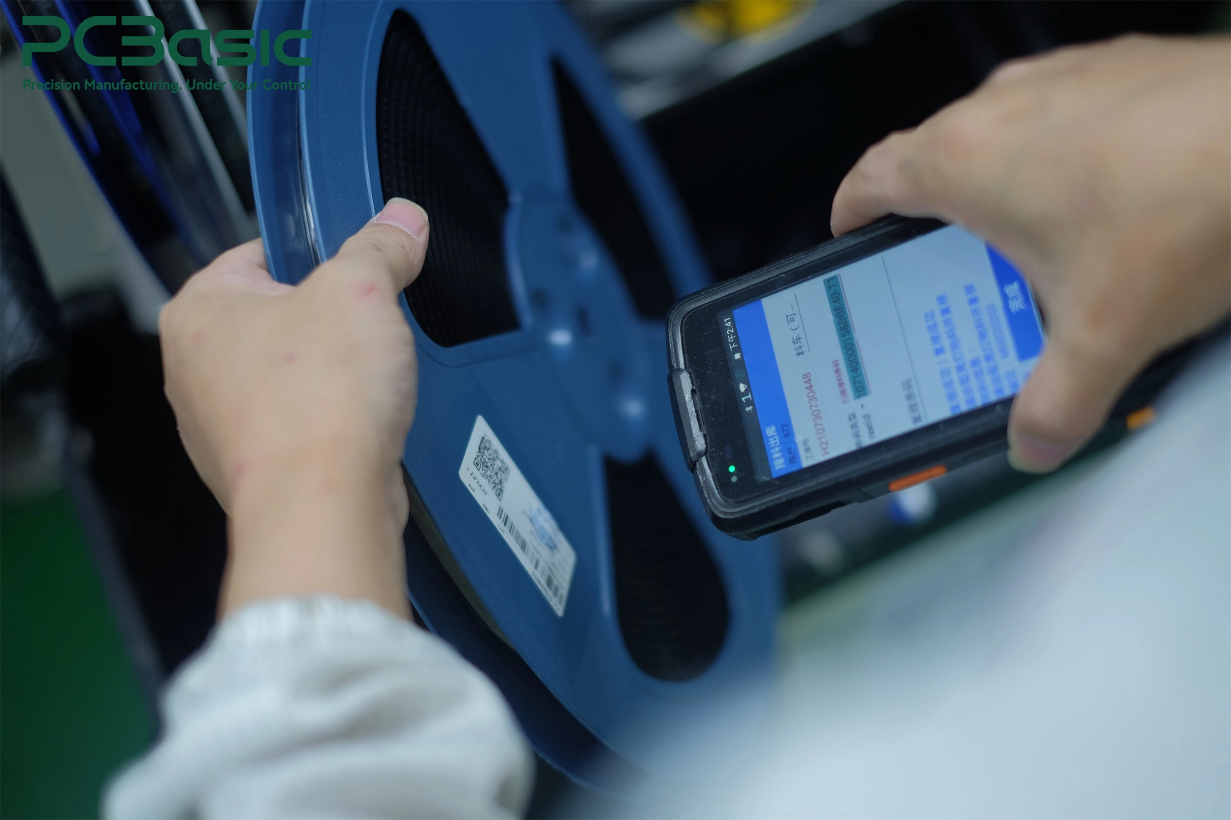
Full traceability links each finished PCBA serial number to specific raw material lots, component reel batch numbers, operator IDs, and manufacturing timestamps. Linking this data simplifies component isolation, helping contain the scope and cost of potential field recalls if a component lot defect is discovered.
• Verification Action: During your facility audit, ask the supplier to perform a live, unannounced barcode lookup. Verify they can trace a random board back to its original component lot numbers within your team's target timeframe (e.g., 10 to 15 minutes).
Processes that cannot be fully verified through visual inspection—such as underfill, selective soldering, or potting—require formal process validation (IQ/OQ/PQ) paired with Process Failure Mode and Effects Analysis (PFMEA). Systematic analysis identifies process drift before non-conforming boards reach clinical testing.
• Trade-off Decision: Quality managers sometimes recommend that ISO 13485 change control apply from the very first prototype build. Product engineers counter that rigid documentation during early prototyping slows iteration. Many teams balance this by running early engineering samples under flexible Engineering Change Orders (ECO), then enforcing complete process freeze before clinical builds or process validation runs.
• Verification Action: Review a sample PFMEA document for special processes (such as underfill or selective soldering) and verify corresponding risk mitigation records in the shop-floor controls.

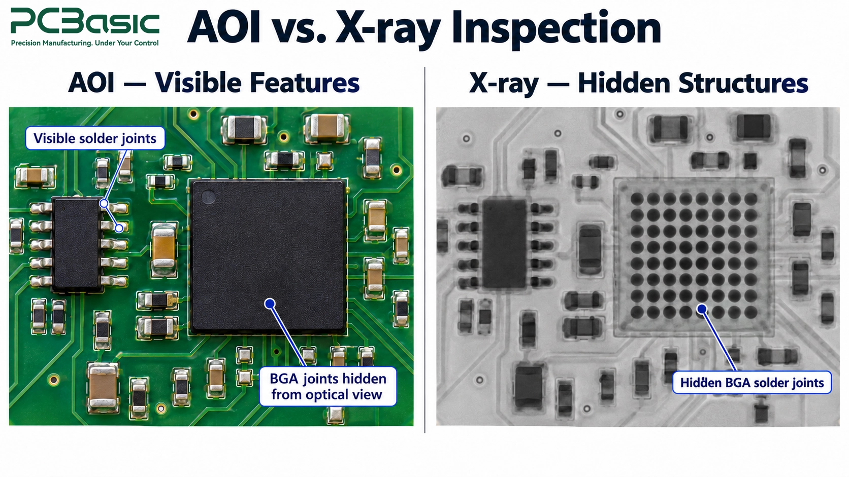
Modern high-density medical PCBAs require 3D Automated Optical Inspection (AOI) and 3D X-ray Inspection (AXI) to analyze hidden solder joints beneath Micro-BGAs and Quad-Flat No-Leads (QFN) packages. Advanced imaging prevents hidden solder bridging and voiding from bypassing end-of-line testing.
• Myth vs. Reality: A visually clean board does not automatically pass IPC Class 3 cleanliness standards. Visual inspections cannot detect invisible ionic residues or microscopic solder flux trapped under dense components. IPC Class 3 references objective chemical cleanliness thresholds, such as surface insulation resistance (SIR) testing and ionic contamination limits (e.g., IPC-TM-650 guidelines).
• Testing Trade-off: Tailor cleanliness requirements to your application environment. Moisture-exposed or high-voltage circuits require rigorous ionic cleanliness testing, while sealed, low-voltage desktop electronics operate reliably under standard no-clean chemistries verified by SIR testing.
• Verification Action: Confirm the shop floor operates dedicated 3D X-ray systems equipped with automated void percentage calculation software rather than relying solely on manual 2D inspection cabinets.
Evaluating candidates based solely on piece-part price risks masking expenses tied to low yields, weak component sourcing, or slow quality resolution. Assess vendor pricing using a Total Cost of Ownership (TCO) model that factors in audit costs, scrap rates, warranty coverage, and long-term regulatory support.
Submitting finalized board layouts to an assembly partner routinely reveals untestable solder pads, poor thermal relief, or uninspectable Micro-BGAs. Engaging your PCBA partner during early layout design (DFMA/DFT) optimizes pad geometries, test point access, and component spacing before freezing your CAD files, preventing expensive re-spins and launch delays.
The checklist below is a supplier evaluation tool. Its acceptance criteria should be agreed for the product and quality agreement; they are not universal regulatory thresholds.
|
Step |
Core Action |
Pass/Fail Criteria |
|
1. Certificate Scope Audit |
Request the supplier's official ISO 13485 certificate and verify issuing body credentials. |
Scope explicitly includes medical PCBA manufacturing; accredited by an established accreditation body (e.g., ANAB, UKAS). |
|
2. Live Traceability Drill |
Ask the team to trace a random board serial number during a live meeting. |
Component lot numbers, operator logs, and inspection records retrieved within the agreed target timeframe. |
|
3. Early DFMA/DFT Review |
Send a sample Gerber and BOM for an initial manufacturability feedback report. |
Vendor identifies real panelization, test-point, or thermal clearance improvements instead of returning an automated pass. |
|
4. On-Site/Virtual Audit |
Inspect inspection equipment, ESD protection controls, and cleanroom maintenance logs. |
Dedicated 3D X-ray capability present; ESD controls strictly monitored; clear physical separation of non-conforming material. |
|
5. Prototype Trial Run |
Issue a low-volume trial order under production documentation protocols. |
Yield meets agreed project benchmarks; comprehensive First Article Inspection (FAI) report included. |
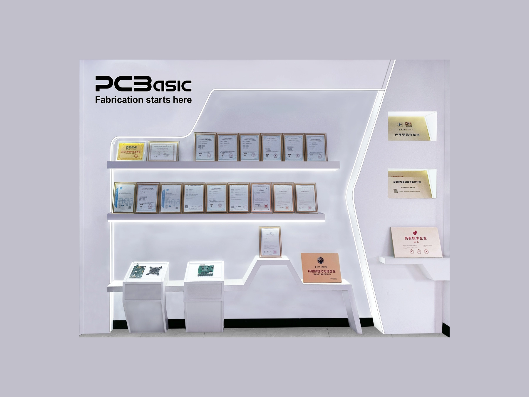
PCBasic provides comprehensive medical device PCB assembly services—covering PCB manufacturing, component sourcing, SMT and through-hole assembly, and multi-stage testing—backed by ISO 13485 certification and deep expertise in high-mix, small-to-medium batch production from prototypes through volume manufacturing.
• Digital Traceability and MES Support: PCBasic’s self-developed Manufacturing Execution System (MES) assigns each board a unique identifier to track its production history from material intake to final delivery. Automated data collection captures process parameters, operator logs, equipment details, SPI, AOI, and functional test results, delivering the transparent documentation needed for quality investigations and manufacturing record reviews.
• Proactive Engineering and DFMA Engagement: Before production commitment, PCBasic’s engineering team conducts thorough pre-production reviews of Gerber files, BOMs, and assembly drawings. Detailed DFMA/DFT feedback addresses pad design, stencil parameters, solder paste thickness, and test-point access, allowing development teams to resolve constraints early.
• Multi-Tiered Inspection and Testing: PCBasic's quality infrastructure includes Solder Paste Inspection (SPI), online AOI, First Article Inspection (FAI), and 3D X-ray inspection for concealed solder joints beneath dense packages. Depending on project stages and device requirements, testing capabilities span flying-probe testing, ICT, customized functional testing, and selective environmental or burn-in testing options tailored to your board design.

Evaluating a medical PCBA partner requires focusing on verifiable shop-floor practices, explicit quality scopes, and early manufacturing feedback. Rather than treating board assembly as a commodity purchase, aligning with a partner who maintains rigorous documentation and clear process validation ensures that your manufacturing evidence remains robust throughout the device's lifecycle.
Q1: Can we use a low-volume prototype shop before transferring to a medical EMS partner?
Quick-turn prototype shops can produce early functional proof-of-concept units. However, engineering builds intended for design verification, clinical trials, or regulatory submissions are best manufactured under ISO 13485 controls. Transitioning to your long-term medical PCBA partner early reduces duplicate qualification expenses and minimizes process discrepancies during scale-up.
Q2: How do we protect our intellectual property when working with overseas PCBA partners?
Protecting IP requires enforceable non-disclosure agreements (NDAs), segmented design documentation, and strict access controls. Limit file transfers to manufacturing-essential Gerbers and netlists rather than raw CAD source files. Working with suppliers operating under clear legal jurisdictions or dual-shore facilities provides additional risk mitigation.
Q3: How do we determine if our device requires IPC-A-610 Class 3 or if Class 2 is sufficient?
Class 3 is recommended for life-support, implantable, or high-reliability diagnostic electronics where downtime cannot be tolerated. For non-critical Class I devices or diagnostic hardware used in benign environments, IPC Class 2 may provide an adequate level of quality while managing costs, depending on your risk analysis.

Assembly Enquiry
Instant Quote


Phone contact

+86-755-27218592
In addition, we've prepared a Help Center. We recommend checking it before reaching out, as your question and its answer may already be clearly explained there.
Wechat Support

In addition, we've prepared a Help Center. We recommend checking it before reaching out, as your question and its answer may already be clearly explained there.
WhatsApp Support

In addition, we've prepared a Help Center. We recommend checking it before reaching out, as your question and its answer may already be clearly explained there.
