
Global high-mix volume high-speed PCBA manufacturer
9:00 -18:00, Mon. - Fri. (GMT+8)
9:00 -12:00, Sat. (GMT+8)
(Except Chinese public holidays)





HomePage > Blog > Knowledge Base > How Can PCBA Manufacturing Prevent Mechanical Damage?
Table of Contents
1. Which forces must a PCBA withstand?
2. How should assembly fixtures prevent board bending?
3. How can soldering and depaneling preserve mechanical strength?
4. Which tests confirm the chosen manufacturing controls?
5. How should the approved build carry into repeat orders?
Support the board where the operation loads it to protect PCBA reliability. If connector insertion, panel separation, or enclosure assembly bends the board, specify a control for that operation; a later successful power-on check does not demonstrate acceptable mechanical loading. At PCBasic, we carry out process review and fixture preparation in the manufacturing route that includes machine depaneling, final assembly, and functional testing. For an OEM engineer, the assembly-file review is an opportunity to address these mechanical requirements before a finished board is fitted into its enclosure.
The first decision concerns the loads the board is intended to carry. Loads beyond that intended capacity need additional structural support, and the approved arrangement needs a defined means of verification. Board thickness, solder quantity, and coating each have their purposes; selecting them does not complete the decision about support.
Use the assembly drawing to review the installed board together with its cables, mating connectors, mounting points, and enclosure-mounted parts. Gerber files do not fully describe the act of plugging in a connector or the restraint supplied by an enclosure. The drawing should fill those gaps and identify where a fixture is allowed to contact the assembly.
Connector insertion can bend the board when the support is distant from the connector. Mount alignment matters separately: a board fastened to misaligned enclosure mounts may already be distorted when it is first powered. Resolve the path for these forces through the approved mounting structure. Adding solder at the connector cannot correct the mount alignment or shorten the unsupported length of the board.
A fixture carries the part during the manufacturing operation for which it is used. In the installed product, support comes from the mounting structure, which determines the part's response there. A review must therefore distinguish the manufacturing condition from the transport and operating conditions. The part can be the same while its loading condition changes.
A bending board changes the relative positions of a component's attachment points. The resulting stress can reach its solder joints, pads, or body, depending on the package and the load applied. For ceramic parts, checking electrical continuity through the soldered connection leaves a separate question to answer: is the ceramic body mechanically undamaged?
In Technical Bulletin 26-10, NASA NESC examines ceramic chip-resistor body cracking. The possible contributors discussed include bow or twist during manufacture or installation, a rigid mounting arrangement, and the fastener tightening pattern. The prevention review consequently needs to consider assembly geometry. No universal board-strain limit is established by that bulletin, and it does not justify identifying vibration fatigue as the cause of every similar failure.
Read the PCB reliability overview for the wider range of failure mechanisms. To address prevention during manufacture, first mark the vulnerable areas and identify the operations that load each one. Those markings provide the starting point for choosing fixtures and inspection.
The fixture review needs a drawing that locates the forces from connector insertion, probe contact, and fastening tools for the operation concerned. Firm clamping at the board's perimeter can coexist with deflection at its centre when force is applied there. Edge clamping by itself therefore does not verify that the whole board remains flat.
A fixture drawing needs both dimensions and a definition of allowable contact. Underside components, joints, test points and keep-outs restrict the available support positions. Support closer to a load can reduce bending, although contact with an unsuitable component can damage that component. Check the loading and unloading movements as part of the arrangement, ensuring that removal does not bend the protected area.
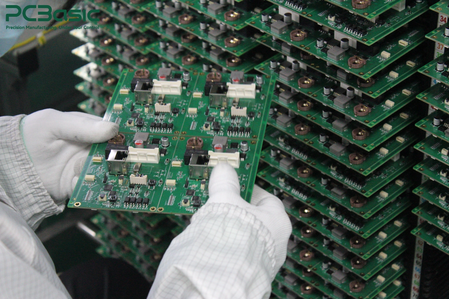
Send the mounting drawing and underside clearances with the test-point layout for our customised fixture review. We prepare production fixtures at PCBasic and have a functional-test fixture manufacturing centre. Electrical contact and mechanical support can consequently be reviewed together, including where testing requires connector mating or simultaneous contact from several probes.
Decide whether the force is intended to pass through a terminal, mounting tab, bracket or enclosure. One feature can serve as both an electrical connection and a retainer when it fulfils the requirements of each. Until the requirement is defined, a soldered terminal must not be assumed to withstand a cable pull or to restrain an unsupported component's movement.
The drawing for a bracket or restraint needs its attachment points and clearances, together with the order of installation. Its load path must not impose damaging stress on neighbouring fragile components, and access for inspection must remain available. Where the restraint is bonded, its material and process require engineering approval. Specifying conformal coating does not approve an adhesive or establish approval of the retention design.
Identify the restraint's supplier and installer in the manufacturing package. Installation by the customer at the enclosure stage changes who does the work, but the restraint is still part of the mechanical configuration even though it is not installed by the PCBA supplier. Describe the interface in the package so that a downstream operation is not left undefined for the soldered board to accommodate.
Assess the fillet using the manufacturer’s soldering requirements for that component and the approved assembly criteria. Even a correctly produced joint leaves unrelated mounting weaknesses to be resolved. Extra solder added to make a part appear stronger may alter the transmission of board movement into its body.
Solder at the top of the ceramic resistor's terminations was one possible contributor discussed by NESC. It could make the connection rigid enough to transmit board flexure into the ceramic. Joint control should consequently follow the requirements of the component actually being assembled. That resistor case does not establish a single fillet specification applicable to all packages.
Solder-paste inspection, first-article inspection, reflow temperature profiling, AOI and X-ray inspection are available within PCBasic's manufacturing route. Select checks to suit the package and the visibility of its joints. A fillet assessment or inspection image gives evidence about the inspected condition. The earlier support and retention choices still help determine whether the mechanical load reaching the joint during assembly remains within acceptable limits.
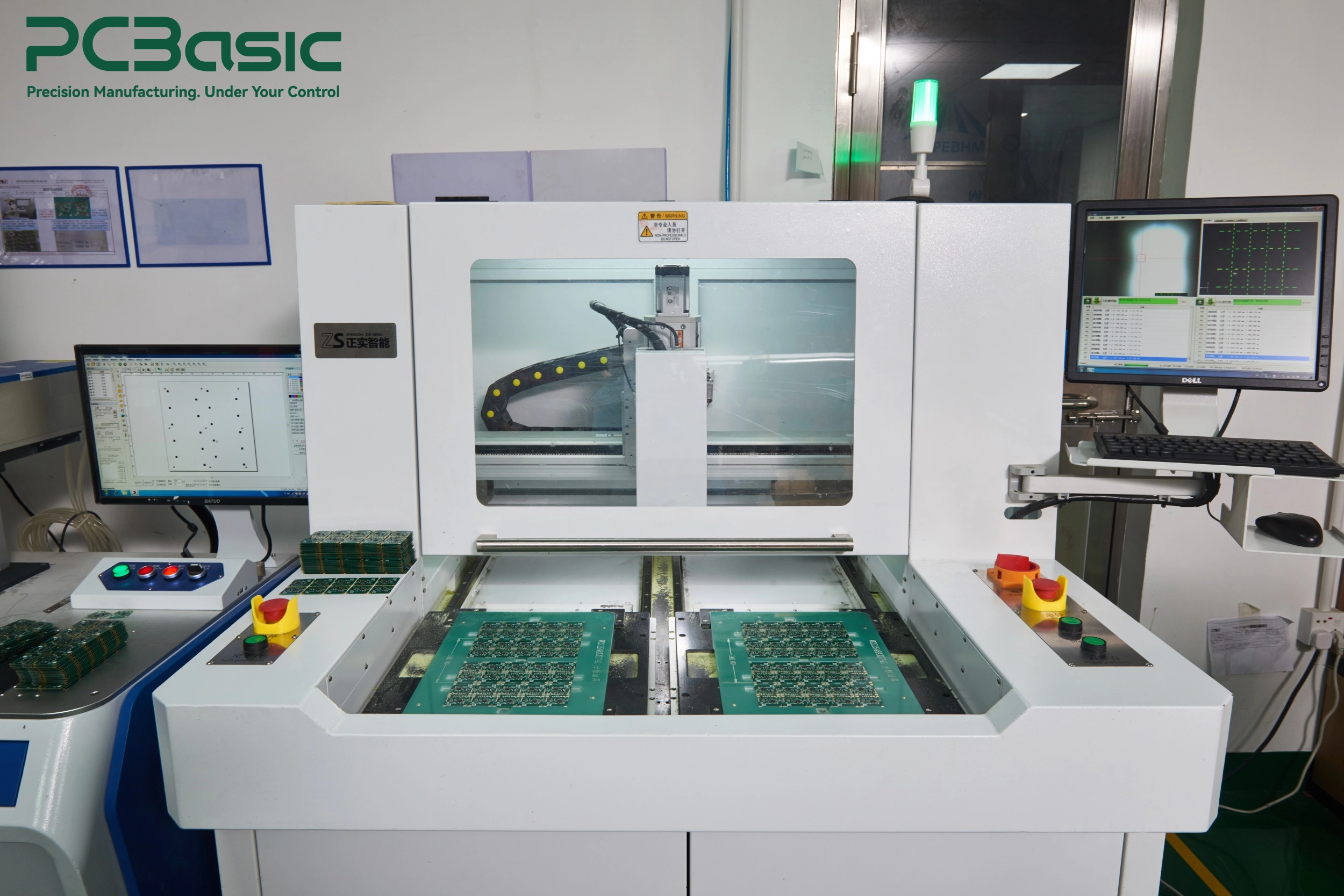
A populated panel has to become separate assemblies, with handling close to the completed joints. Choose the separation method to suit the panel features, component locations, and surfaces available for support. Flexing the populated panel to finish the separation can load vulnerable parts whose soldering was otherwise acceptable.
We include separation in the assembly route and use depaneling equipment at PCBasic. Provide the panel drawing, separation features, and component clearances for review before production starts. Define support during the cut or separation, together with the way the released assembly is held. Machine settings and edge clearances must suit that assembly; a value appropriate to another board is not an approval.
Include removal from the holder and transfer into the test fixture in the handling review after separation. Either movement may bend a board that was intact when separated. Retain the agreed method in the job instructions and check the whole movement. PCBA mechanical strength must be preserved beyond the condition observed just after reflow.

Define the assembly being approved and the configuration represented by the sample before selecting its test. The freedom of movement differs for a loose board, a mounted board, and an enclosed product. A result for one arrangement therefore does not automatically apply to the others.
We use PCBA testing at PCBasic to identify structural weaknesses through vibration testing, and to assess solder-joint integrity, component stability and shock resistance through drop testing. Planning either one requires the mounting arrangement, loads or stress profile, duration or repetitions, and acceptance criteria to be specified. Agree how the sample represents any cable, bracket, or enclosure that the customer will add after delivery.
Test selection follows the failure mechanism expected in the application. The highest available stress alone is not a reason to select a test. A pass with unexplained conditions offers little guidance for repeat production, whereas a result under defined conditions can support changes to retention or support. Its evidence covers that tested arrangement and those conditions, without establishing unrestricted service life.
Take the initial electrical result as the baseline for comparison after mechanical loading, with in-test monitoring where needed to detect intermittent faults. Where a direct comparison is intended, keep firmware, test programme, inputs and loads consistent. Include any interface whose continuity or response might change if a connector moves or damage occurs beside the loaded area.
We define power-up, signal-response, interface, and logic checks for functional testing at PCBasic according to the project requirements. To compare the assessment before and after loading, provide the expected responses and their limits. Keep any abnormal response in the record, including one followed by an apparently normal room-temperature check.
Inspection covers conditions that a functional check may not cover in the same way. Visible defects, intermittent responses and faults occurring only under stress can require different investigations. Use the result to help identify the implicated manufacturing operation or mounting interface. Another test run does not remove the cause while that suspected mechanism is still unresolved.
Keep a concise mechanical control plan with the assembly instructions. It should state the support or handling control that makes each operation acceptable. This gives the production team a defined way of consistently meeting PCBA durability requirements in place of a general request to improve durability.
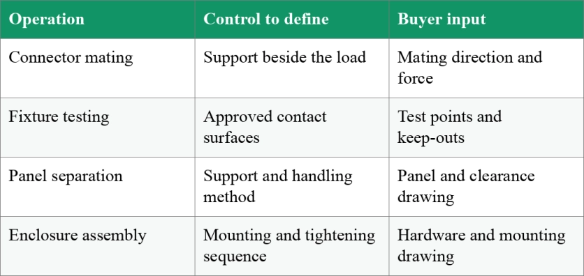
PCBasic's production route covers process evaluation, fixture preparation, depaneling, testing, and final assembly. Review their requirements together: an arrangement agreed for one operation also needs to accommodate the next. Where another party completes assembly, define the handover condition and allocate responsibility for fastening or restraint that remains to be done.
Review a replacement connector for differences in mating force and access, and a changed enclosure for differences in mounting. A fixture revision can reposition support even with no circuit or BOM change. Compare the revised build with the approved version and establish whether the earlier test evidence still applies. Approval must not simply be carried forward automatically.
Our MES and inspection systems are used to monitor production and provide traceability. Agree the job-record content for fixture revision, assembly instructions, material changes, and test results so that the version built and checked can be identified. When that version changes, engineering review must decide if additional verification is needed. The record makes that decision retrievable; it does not carry out the review.

Include the support, retention, and assembly sequence with the circuit files for review when they determine mechanical integrity. Send the revision-controlled Gerber files and BOM, mounting and assembly drawings, connector and heavy-component loading information, build quantity, and test acceptance criteria for an assembly project review. PCBasic can consider fixture preparation, depaneling, final assembly, and testing together in assessing the production route, before the build configuration is approved.
Q1: Does a passed mechanical test guarantee PCBA service life?
A1: No. A pass applies to the arrangement used in that test, under its stated stress conditions and acceptance criteria. Assessing service life also requires the intended environment and its relevant failure mechanisms to be considered. Review the applicability of the earlier result whenever the mounting or a component changes.
Q2: Is a thicker board the best way to improve PCBA mechanical strength?
A2: Consider thickness alongside mounting geometry, component requirements, and fixture interfaces. An incompatible mounting arrangement can distort a thicker board too. Establish the points where loads enter the assembly and the support available there before choosing the appropriate board construction.
Q3: Can conformal coating replace a mechanical support or restraint?
A3: Specifying a coating for environmental protection does not settle how the assembly carries force. Use an approved mechanical arrangement where structural retention is needed, with separate approval of any proposed material and process. Include access, inspection, and repair requirements within that review.

Assembly Enquiry
Instant Quote




Phone contact

+86-755-27218592
In addition, we've prepared a Help Center. We recommend checking it before reaching out, as your question and its answer may already be clearly explained there.
Wechat Support

In addition, we've prepared a Help Center. We recommend checking it before reaching out, as your question and its answer may already be clearly explained there.
WhatsApp Support

In addition, we've prepared a Help Center. We recommend checking it before reaching out, as your question and its answer may already be clearly explained there.
