Table of Contents
1. Why Do Solar Energy PCBAs Need High-Current Manufacturing Checks?
2. What Should Buyers Confirm for Solar Inverter PCB Assembly?
3. How Should BMS and Charging Module PCBA Be Reviewed?
4. What Manufacturing Checks Should Buyers Put Into the RFQ?
5. How Can PCBasic Support High-Current PCBA manufacturing?
6. Conclusion
7. FAQs
High-current PCBA used in
solar energy systems should not be treated as ordinary assembled circuit
boards. Unlike ordinary control boards, these PCBA often simultaneously perform
functions such as energy conversion, current transmission, heat management and
safety protection. In actual solar and energy storage devices, they usually
appear in key positions such as Solar inverter PCB assembly, BMS and charging module PCB assembly. For these
modules, normal short-time power-on does not mean that manufacturing risks have
been eliminated.
Before production begins,
buyers need to confirm the current path, heat dissipation path, power device
fixation method, SMT and DIP process planning, test requirements and batch
traceability. Inverters and charging modules usually pay more attention to high-current
paths, power device welding and temperature rise control; while BMS PCBA pays
more attention to sampling, protection, balancing, communication, and in some
designs, risks related to the main battery current path.
These inspections have an
impact on initial quotes, process assessments, and delivery risk assessments in
addition to representing the quality standards during the production stage. For
high-current PCBAs, a basic price based on quantity and BOM is sometimes
insufficient. The BOM can show which materials are used, but it cannot
accurately represent production concerns such batch uniformity, heat
dissipation, power device installation, and test coverage.
If alternative materials,
soldering quality, heat transfer paths, or test standards are not checked
beforehand, problems can persist in subsequent production batches. Therefore,
customers are best prepared with board files, BOM, power device descriptions,
test expectations, and repeat order requirements before producing quotations
and beginning production. However, data preparation is only the first step.
More important is the supplier's ability to implement these standards in the
actual manufacturing process, which includes PCB manufacturing, component
procurement, assembly, testing, production records, and future repeat order
management.
When PCBasic is involved in PCBA projects related to power supplies, it not only
focuses on basic PCB assembly, but also integrates the entire process including
PCB manufacturing, component procurement, assembly, testing and production
records. When comparing PCB assembly services, buyers should comprehensively
consider the ability of the supplier to continuously control design
requirements, procurement risks, inspection steps and testing
procedures from sample production to subsequent production, as well as their
actual circuit board assembly capabilities.
Why Do Solar Energy PCBAs Need High-Current Manufacturing Checks?
The solar inverter circuit board and charging
module usually consist of power conversion, switching
devices, control circuits, protection logic, connection components and
heat-generating elements. The BMS board, on the other hand, focuses more on
battery monitoring, temperature and current sensing, battery cell balancing,
protection logic, communication, and safety control.
These PCBA components often need to operate
continuously for long periods of time. Some projects may also be affected by
factors such as humidity, temperature fluctuations, vibrations, or the external
environment of the cabinet. Therefore, the pre-production manufacturing review
must not only focus on the bill of materials (BOM) and assembly difficulties,
but also anticipate the manufacturing risks brought about by current heat
dissipation, protection, and environmental adaptabilit
Power Paths Need Clear Current and Thermal Rules
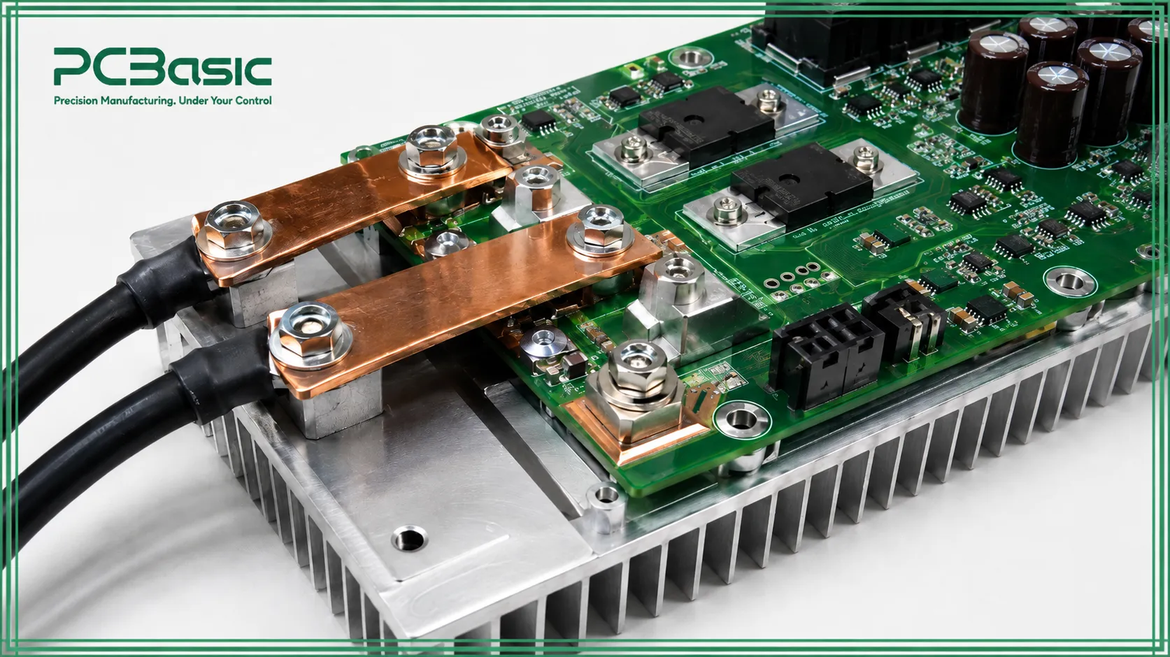
The first thing the customer needs to confirm is the current path. For high-current PCBAs, just having the lines connected is not enough; it also depends on factors such as copper thickness, trace width, electrical spacing, connector current rating, copper plating area, layer structure, and heat dissipation path to ensure they are suitable for the actual load.
Some layouts may look acceptable on paper, but if the current is concentrated in a certain trace section, the welding area is insufficient, or the connector position is inappropriate, local overheating may still occur when the board is in operation. It is more reliable to review these positions before production rather than checking the temperature rise after the sample is completed. Solar inverter PCB assembly and charging module both require a clear heat dissipation solution. MOSFETs, IGBTs, diodes, relays, transformers, power inductors, high-current connectors, and some capacitors may all become local hotspots.
For such high-current PCBA products, buyers do not need to prepare an RFQ as a complete design report, but at least they should indicate which areas carry high current and which components are sensitive to temperature rise. This way, when the supplier evaluates the process, welding method, component fixation and test plan, they can take the heat dissipation risks into account together. If there are issues such as overheating, abnormal temperature rise of connectors, or unstable operation during the sample stage, simply re-quoting or arranging for the next batch of production usually cannot solve the fundamental problem. We usually recommend that you first re-evaluate the power path, welding area, connector position, and heat dissipation path to determine if the problem is related to current distribution or insufficient thermal design.
Control Areas Should Be Separated From Noisy Power Sections
Solar-powered PCBAs are not merely responsible for handling high currents and power conversion. Many boards also integrate control, sampling, monitoring, and communication circuits simultaneously. For instance, in the BMS PCBAs, voltage sampling, current sampling, temperature sampling, equalization circuits, and protection logic may be placed relatively close to the main power path, especially when the board is directly connected to the battery main circuit.
The charging module also has a similar situation. The control circuit may need to be placed on the same board as the switching devices, heat-generating devices, and high-current connectors. If these areas are not clearly distinguished in advance, subsequent problems such as inaccurate sampling, unstable communication, or abnormal protection logic may occur.Therefore, the buyer needs to inform the supplier in advance which areas require stable and low-noise signals, and which areas need to handle high currents. Only in this way can the engineering team conduct targeted reviews of grounding, wiring, test points, connector positions and inspection priorities. If the board also has CAN, RS-485, UART, Ethernet or indication functions, the pre-delivery tests should also cover these communication, indication and protection-related functions to avoid subsequent problems such as inaccurate sampling, unstable communication or abnormal protection logic.
Long-Run Use Changes the Review Standard
Solar inverters, energy storage cabinets or charging modules usually require operation for a longer period than short-life-cycle consumer devices. Therefore, buyers should not only consider whether the first sample passes, but also pay attention to the consistency of subsequent repeated production. When the next re-order production is carried out, the BOM version, confirmed substitute materials, inspection records and test rules should all be able to continue to be used, rather than being re-confirmed for each batch.
Therefore, Energy Storage PCB Assembly should not be regarded merely as simple circuit board assembly. It should be regarded more as
a controlled manufacturing process, covering aspects such as component
procurement, SMT/DIP assembly, test records and batch traceability.
What Should Buyers Confirm for Solar Inverter PCB Assembly?
Solar inverter PCB assembly cannot be judged
merely by whether the board can be installed properly and whether it can be
powered on. Compared with ordinary control boards, the inverter board usually contains more high-current components, heat-generating components and protection circuits. As long as a component is wrongly selected, the welding is unstable, or the testing conditions are not clearly stated in advance, problems such as overheating, abnormal protection or batch instability may occur later.
Therefore, before production, buyers need to focus on confirming several issues: whether the current and heat dissipation are matched, whether the key power components are controlled, whether the SMT and DIP processes are separately planned, and whether the testing requirements are clear.
Copper Distribution and Spacing Should Match the Power Stage
The power stage requires a focused review of the current-carrying capacity, electrical spacing, heat dissipation, and connection points. If there are large current connectors, bus input terminals, or large power devices on the board, the supplier needs to understand the actual usage method of this board and the heat that may be generated during operation.
For power-related PCBA, the manufacturing review cannot only focus on Gerber files. In addition to the conventional DFM, it is also necessary to confirm assembly requirements, test interfaces, component height limits, heat sink contact areas, screw holes and connector positions, as well as whether jigs are required. If these pieces of information are missing, the supplier may still be able to quote, but it is likely to overlook the risk points that truly affect the stability of production.
Power Components Need Sourcing Control
Power devices should not be treated merely as ordinary components in the bill of materials. MOSFETs, IGBTs, capacitors, diodes, relays, inductors, sensors and high-current connectors can all affect the overall reliability, temperature rise performance, protection response, certification preparation and mechanical assembly of the entire product. Substitutes with similar parameters on paper may not perform the same way when installed in the final product.
Therefore, buyers need to clearly indicate in advance which components are locked and cannot be replaced. If a certain component allows for replacement, the approved substitute materials should be included in the BOM or formally confirmed in the records. This way, the supplier can determine which materials can be adjusted and which ones cannot be changed at will, and also be able to control risks in advance during the electronic component sourcing stage.
SMT and DIP Steps Should Be Planned Separately
Many solar inverter boards will use both SMT and DIP assembly processes simultaneously. Smaller control and signal components usually go through the SMT process, while larger components such as connectors, relays, transformers, large capacitors, and high-current terminals often require DIP or through-hole soldering. These two processes need to be coordinated together, but they cannot simply be treated as the same assembly process.
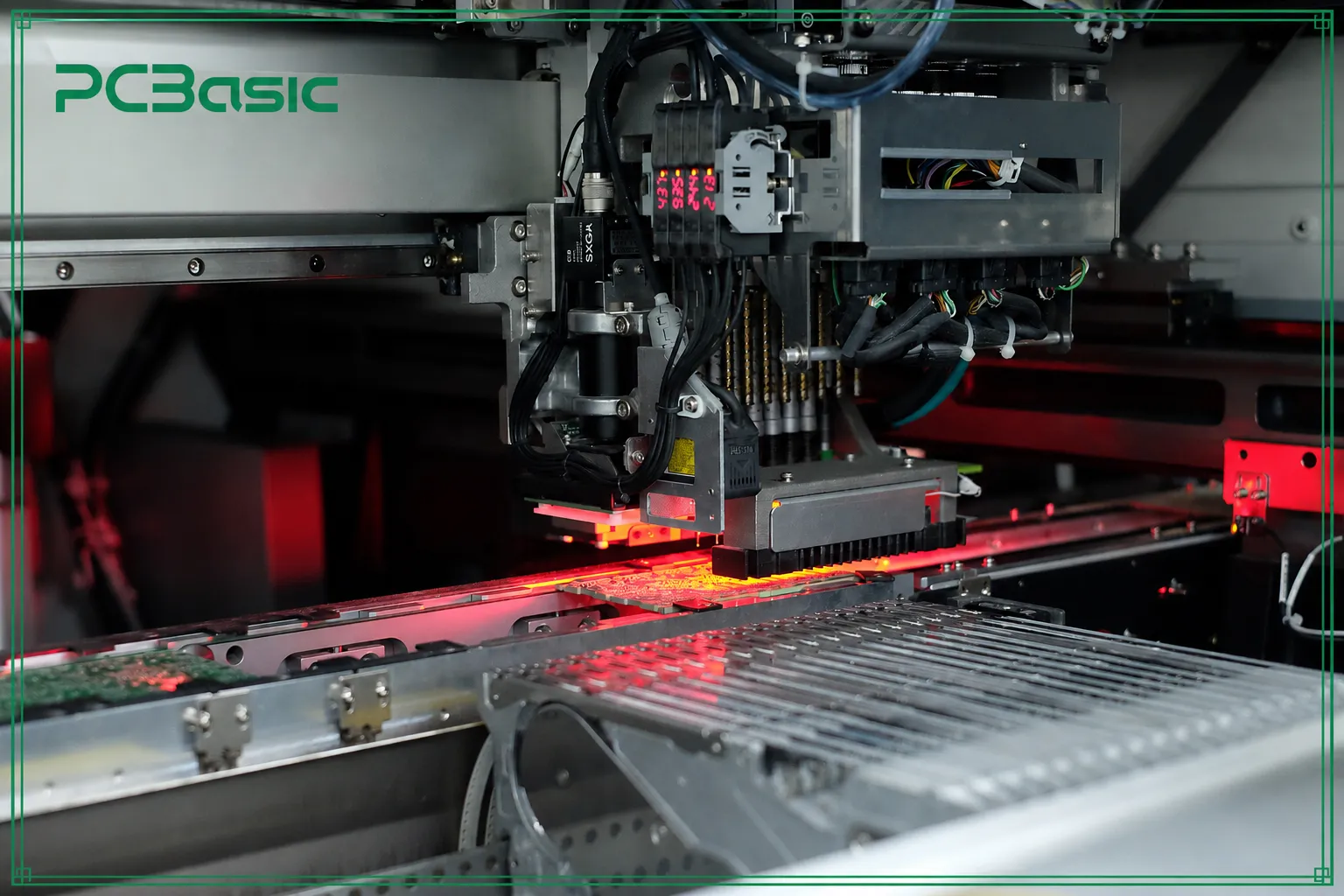
The SMT assembly usually involves solder paste printing, mounting, reflow soldering, as well as inspection steps such as SPI and AOI; in some cases, first-piece inspection is also necessary. If there are BGA, QFN or other hidden solder joints on the board, X-ray inspection should also be included in the inspection plan in advance. After assembly is completed, the electrical testing of the PCBA may include power-on testing, firmware inspection, interface verification, and necessary load response tests. Clearly distinguishing the
SMT, DIP, inspection and testing items in advance can reduce the
misunderstanding between buyers and suppliers regarding the scope of testing.
How Should BMS and Charging Module PCBA Be Reviewed?
The inspection focus for the BMS and charging
module projects is not exactly the same as that for the inverter power board. These boards may not have as large power components and heat dissipation structures as the inverter power board, but factors such as measurement accuracy, protection response, current detection, firmware version, and control logic can all affect the safety, operational stability, and consistency of subsequent rework production of the final product. Therefore, during the review process, it is not only necessary to consider the assembly difficulty, but also to ensure that the measurement, protection, communication, and testing requirements have been clearly defined in advance.
Battery Management System PCBA Needs Measurement Accuracy
The risks in Battery Management System (BMS) PCBA often extend beyond the power path; they also involve the stability of sampling, protection, and communication functions. Before production, it is necessary to confirm the key components, test items, and determination criteria corresponding to these functions to avoid discovering sampling deviations, abnormal protection responses, or unstable communication after the board is assembled.
During the specific review process, the buyer should ask the supplier to distinguish between the measurement circuit and the power area that carries large currents, and confirm which components require strict procurement control, which signals must be verified before shipment, and whether firmware checks and communication checks should be included in the production tests. In this way, during subsequent rework production, the supplier can control consistency by following the same set of materials, testing and determination rules.
Charging Module PCB Assembly Needs Low-Impedance Current Paths
Charging modules PCB assembly of different power ratings have varying requirements for current path impedance, thermal path stability, and the layout of MOSFETs, diodes, inductors, capacitors, connectors, and sensing devices. If these important components are not examined beforehand, the board may pass a basic visual examination yet have high heat production or voltage drop issues during actual load performance.
In addition, the new energy power module PCBA requires a clear maintenance and retest process. After repairing a high current solder joint, the re-repaired product should undergo additional testing and inspection. If the re-repaired circuit board is mixed with the regular circuit board without the necessary documentation, future batch evaluation and problem tracing will become much more difficult.
Functional Testing Should Be Defined Before Batch Build
Before batch testing begins, the buyer and supplier should first clarify the test content, including power-on status, firmware version, operating status, protection response, indicator light performance, communication interface and load response. The purpose of the test is not to reproduce every on-site usage condition, but to identify in advance those fault modes that may affect shipment or installation.
Whether it is the solar inverter PCB assembly, BMS PCBA, or the charging module PCB assembly, the test records should be associated with the BOM version, board version and production batch. In the subsequent problem evaluation, it is difficult to support outcomes that pass or
fail without a batch context.
What Manufacturing Checks Should Buyers Put
Into the RFQ?
A useful RFQ is not merely a tool for suppliers
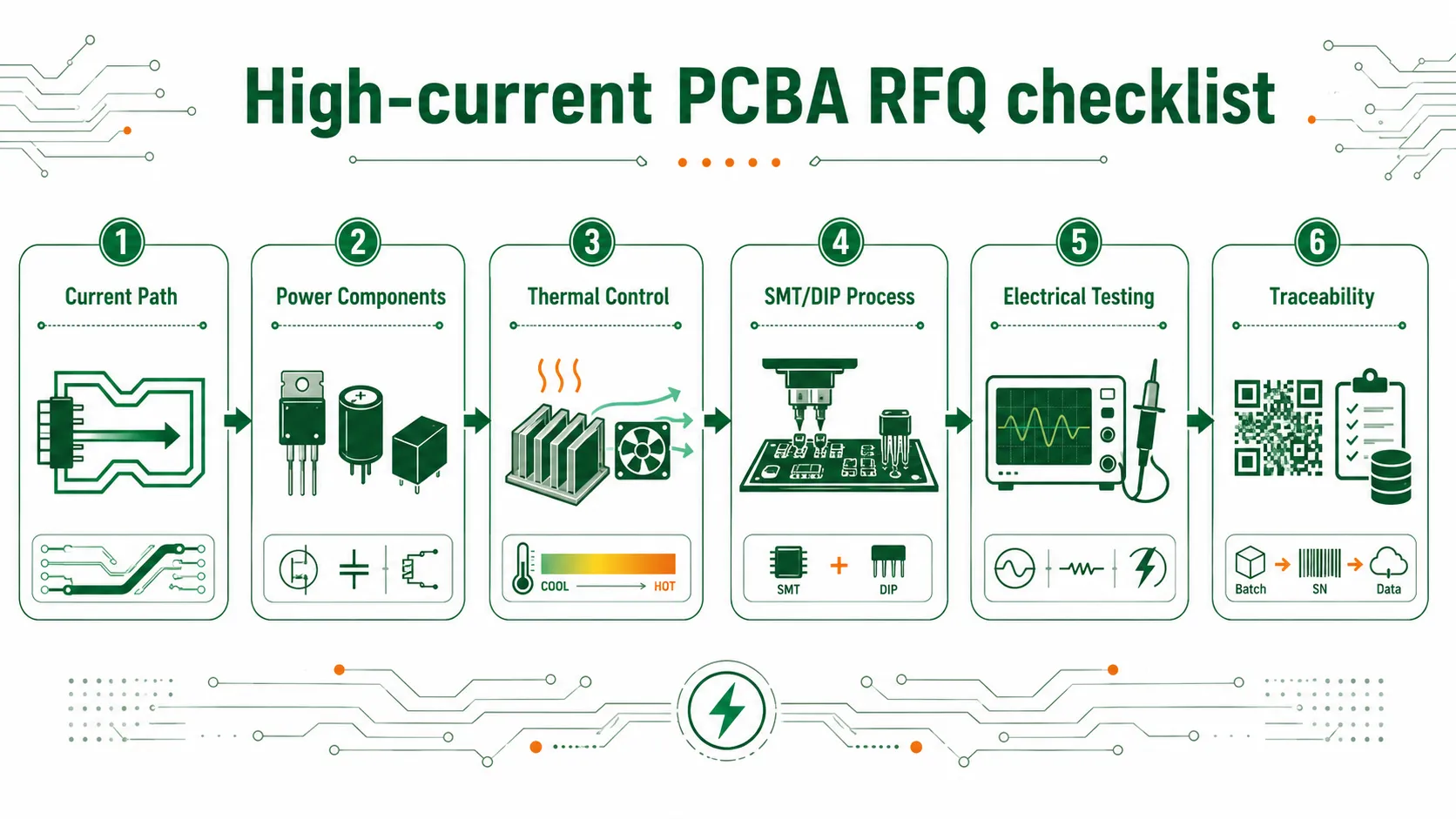
to quickly quote based on Gerber files, BOM and quantities. Instead, it should enable suppliers to clearly understand the actual manufacturing requirements. For high-current PCBAs, many risks do not directly manifest in the BOM. For instance, current paths, power devices, cooling methods, test ranges and traceability requirements.
This information does not need to be written as a complete design report, but should be clearly stated at the RFQ stage. Only in this way can suppliers make evaluations based on actual manufacturing risks instead of making preliminary estimates solely based on documents. The following table can serve as a reference for buyers to check when preparing the RFQ.
|
Manufacturing Check
|
Why It Matters
|
What Buyers
Should Confirm
|
|
Current
path
|
Poor current paths may cause heat or voltage drop
|
Copper
weight, trace width, clearance, connector rating, temperature rise target, thermal path
|
|
Power
components
|
Wrong
substitutes may affect reliability, heat, or fit
|
MOSFET,
IGBT, capacitor, diode, relay, approved alternates, locked parts
|
|
Thermal
control
|
Poor thermal
control affects stability and service life
|
Heat
sink contact, copper area, airflow, thermal pad, operating load, ambient temperature
|
|
Control and
signal areas
|
Noise may affect
sensing, communication, or protection logic
|
Grounding,
signal routing, sensing areas, CAN/RS-485/UART/Ethernet checks
|
|
SMT
and DIP process
|
Mixed
assembly can create
soldering and inspection gaps
|
SMT
inspection, through-hole soldering, wave
soldering or
selective soldering needs
|
|
PCBA
electrical testing
|
Visual
inspection cannot prove electrical
performance
|
Power-on
test, load response,
communication test, firmware check, protection status
|
|
Traceability
|
Repeat
orders need consistent records
|
BOM
version, board revision, component lot, inspection
record, repair and retest result
|
This table can help buyers make a fairer comparison of suppliers. A lower initial quote may not include factors such as tooling preparation, testing time, special material procurement, selective welding or production record requirements. The more clearly the RFQ is
written, the easier it is for suppliers to understand the actual workload
before accepting the order, and it can also reduce the
need for repeated confirmation during the production process.
How Can PCBasic Support High-Current PCBA manufacturing?
For high-current PCBA projects, the
controllability of the manufacturing process does not solely depend on
individual assembly steps. The materials, processes, tests, and records confirmed during the sample stage, if cannot be continued in the subsequent rework production, will easily lead to information breaks between batches.
Therefore, the support focus of PCBasic for such projects is not merely to complete PCB assembly, but to help buyers extend the key manufacturing requirements from the sample stage to subsequent production batches.
PCB Assembly Services Should Connect Fabrication, Sourcing, and Testing
PCB assembly services should not merely focus on the component mounting process. For power-related PCBA projects, PCB manufacturing, component procurement, SMT/DIP assembly, inspection, testing, and production records need to be managed within the same process to reduce information gaps between sample production and rework production.
PCBasic can provide corresponding support for such projects, helping buyers connect key materials, assembly requirements, test records, and batch traceability, rather than having each step handled independently.
When the solar inverter PCBAs move from the sample stage to the rework production process, the previously confirmed BOM version, power components, assembly requirements, test rules and production records must be continued to be used in subsequent batches, rather than being reconfirmed for each order.
Similarly, in new energy power modules PCBA or charging modules PCB assembly project, if there is a need to lock power components, mixed SMT/DIP process steps, or if test records need to be rechecked later, the process connection will directly affect batch consistency and the efficiency of problem traceability.
Traceability Should Answer Batch Questions
For repeat production, traceability should answer practical questions:
·Which BOM version was built?
·Which component lot was used?
·Which inspection record belongs to the batch?
·Which units were repaired and retested?
·Which approved substitute was used?
·Which test result belongs to the production batch?
The quality control system of PCBasic can support such reviews through digital production records and traceability capabilities.
For buyers, what is truly
valuable is not simply saving the records, but being able to quickly trace back
to the corresponding board version, component batch, inspection steps and test
results in case of subsequent problems.

Conclusion
High current PCBA for solar systems should be
subject to manufacturing review as a regulated power supply component and not
treated as a normal assembled circuit board. The purchaser shall confirm the current path, heat dissipation path, locking elements, SMT and DIP process planning, functional testing and traceability requirements prior to production.
If the inquiry only provides the bill of materials (BOM) and quantity, the supplier will have to make many assumptions about manufacturing risks when dealing with projects such as solar inverter PCBA, BMS PCBA, new energy power module PCBA or charging module PCBA. A more reliable approach is to prepare Gerber files, BOM, power component descriptions, test expectations and target production quantities before the final manufacturing review.
If your project is moving from the prototype stage to repeat PCBA manufacturing, you can organize these materials into a file package and send it to PCBasic requesting a manufacturing review. Before the details of procurement, assembly and testing details are finalized, a manufacturing review can be
conducted first to reduce subsequent modifications and batch risks.
FAQs
Q1: What makes solar inverter PCB assembly different from normal PCB assembly?
A1: It usually involves higher current, switching devices, thermal control, power components, mixed SMT/DIP assembly, and clearer testing and traceability records.
Q2: Can PCBasic support Battery Management System (BMS) PCBA projects?
A2: Yes. At PCBasic, we can support PCB fabrication, component sourcing, PCB assembly, testing, and batch records for BMS-related PCBA projects.
Q3: Why is traceability important for charging module PCB assembly?
A3: Traceability connects BOM versions, component lots, inspection results, repairs, retesting, and repeat production records.