Table of Contents
1. Production Starts Before Components Reach the Line
2. Process Control Turns Small Variations Into Big Outcomes
3. Inspection Should Separate SMT Checks From Electrical Testing
4. Traceable Records Connect SMT, Testing, and Box Build
5. Conclusion
6. FAQs
SMT PCB assembly may seem quite simple: applying solder paste, mounting components, reflow soldering, and then conducting tests. Done. However, after participating in batch production projects for some time, we became increasingly clear of one thing: what truly affects the stability of the product is often those details that may not be obvious in the early stages.
Some issues are not obvious during the review process and usually only become apparent after going into production. The parameters of the steel mesh cannot be detected as abnormal in the document, but deviations may occur during actual printing; although the components are placed in the correct position, the orientation may still be incorrect due to inconsistent definitions in the data. The same problem exists with the welding properties and reflow curves of alternative materials -- an accurate judgment cannot be made based on BOM parameters or general processes alone.
When reviewing the SMT project, PCBasic not only focuses on the soldering speed, but also pays attention to whether the first batch of circuit boards can successfully pass the tests. We are more concerned about whether the design documents, actual materials, process parameters and testing requirements have actually been matched before the official commissioning.
Production Starts Before Components Reach the Line
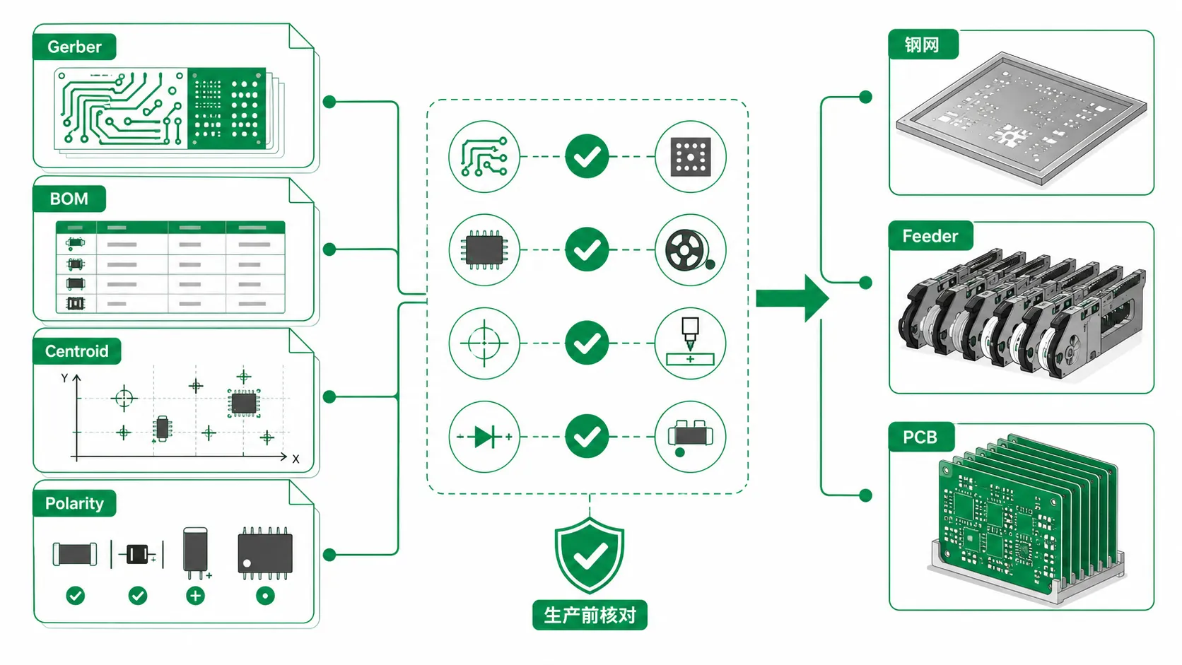
Many people think that loading materials is the first step of SMT production. This is untrue. Before manufacturing began, the engineering team checked the specifications for Gerber files, BOM, coordinate files, and steel mesh. Any difference in these materials might cause problems on the production process.
It is not enough to just check whether the papers have been supplied during the production preparation stage. The BOM's part numbers, packaging, and replacements must match the coordinate data, component orientation, and PCB information. Additionally, the assembly method, stencil apertures, and other process requirements must enable the subsequent loading, mounting, and inspection.
If these problems occur during production, field workers may need to update the solder paste dispensing software, adjust the feeder, or recheck the location numbers. In addition, for sites with compact layouts and fine-pitch integrated circuits, the solder paste release and detection space should be checked ahead of time. If not, the test results may be affected, requiring rework.
Stencil, BOM, and Placement Data Need to Agree Before Production
In real production, we pay attention to the stencil before the line goes live. Solder paste dispensing stability is directly affected by the size and shape of the stencil holes. The possibility of solder bridging, insufficient solder, or tombstoning is increased by improperly sized apertures, all of which result in more rework.
The bill of materials (BOM) is the same—we cannot simply verify whether the part numbers are correct. Matching part numbers is only one aspect of BOM evaluation. Before the project proceeds, it is necessary to verify the package, tolerance, temperature rating, lifecycle status, and allowed alternatives.
Next, placement information is checked against BOM and PCB files, including coordinates, orientation, and reference designators. If the files don't agree, the right section can nonetheless end up in the wrong place. It does occur.
For this reason, we handle stencil, BOM, placement, and sourcing as a single, integrated package in turnkey PCB assembly. Documents shouldn't be the only thing reviewed. Purchasing and manufacturing preparation must take it into account. If not, discrepancies that may have been discovered earlier only become apparent when the line is set to run.
Taking PCBasic as an example, we review the documents submitted by clients item by item, taking into account actual procurement conditions and production requirements. We often buy components from original manufacturers and authorized distribution channels in addition to maintaining frequently used goods in stock. This ensures a more efficient procedure for BOM matching and material preparation, as well as a reduction in production schedule disruptions caused by delays in acquiring frequently used components.
Process Control Turns Small Variations Into Big Outcomes
SMT manufacturing requires extremely high process precision; even small deviations can cause problems with weld quality or reliability in the later stages.
During solder paste printing, the thickness, area, and placement of the solder paste must be controlled; as the component is being placed, components must be accurately placed on their corresponding pads. During the reflow soldering process, it is necessary to form stable solder joints at multiple locations. At the same time, it is essential to prevent situations such as excessive temperatures, insufficient wetting of the surfaces, or incomplete formation of solder joints.
However, in actual production, it cannot be limited to these three processes. It's all related. A single process chain includes formwork, solder paste condition, feed settings, patch method, nozzle condition, reflow profile, and post-reflow detection. If the parameters of the initial stage are not properly controlled, subsequent welding and inspection operations are likely to be affected.
The manufacturing window is further limited when the board has BGAs, tiny passives, fine-pitch connectors, or pads with substantial thermal mass changes. Some boards may seem OK at first, but they may eventually show little issues like poor solder joints, poor connections, or inconsistent and challenging-to-replicate test results.
Solder Paste Printing Sets the First Quality Boundary
When we inspect soldering issues on site, we often trace the cause back to the end, only to find that the problem actually lies in solder paste printing, not in SMD or reflow soldering.
Too much solder paste print makes it easier to solder the fine-pitched pins; If too little is printed, the solder joints may not be strong enough. Even if the stencil itself is fine, unstable solder paste release may cause variations in solder content across different pads.
This is also why many factories conduct a check-up after printing rather than directly entering the placement stage. Because at this point, if problems are found, it's easier to adjust parameters or reprint; Once components have been attached, reworking them will be much more costly and time-consuming.
Reflow Control Affects More Than Solder Appearance
Reflow welding cannot apply only one fixed curve. In actual production, we adjust the parameters according to PCB material, copper layer distribution, component heat absorption, and temperature requirements of tin paste and device. Even for the same project, the original setup may need to be reconfirmed as long as the copper layer thickens or the connector changes.
For repeat orders, we will not simply copy the settings from the previous batch. Before production, the engineer will check the previous furnace temperature curve and production record, and then confirm whether there are any changes in the PCB, components or connectors this time. If the plate substructure is adjusted, the original reflux parameters also need to be re-checked.
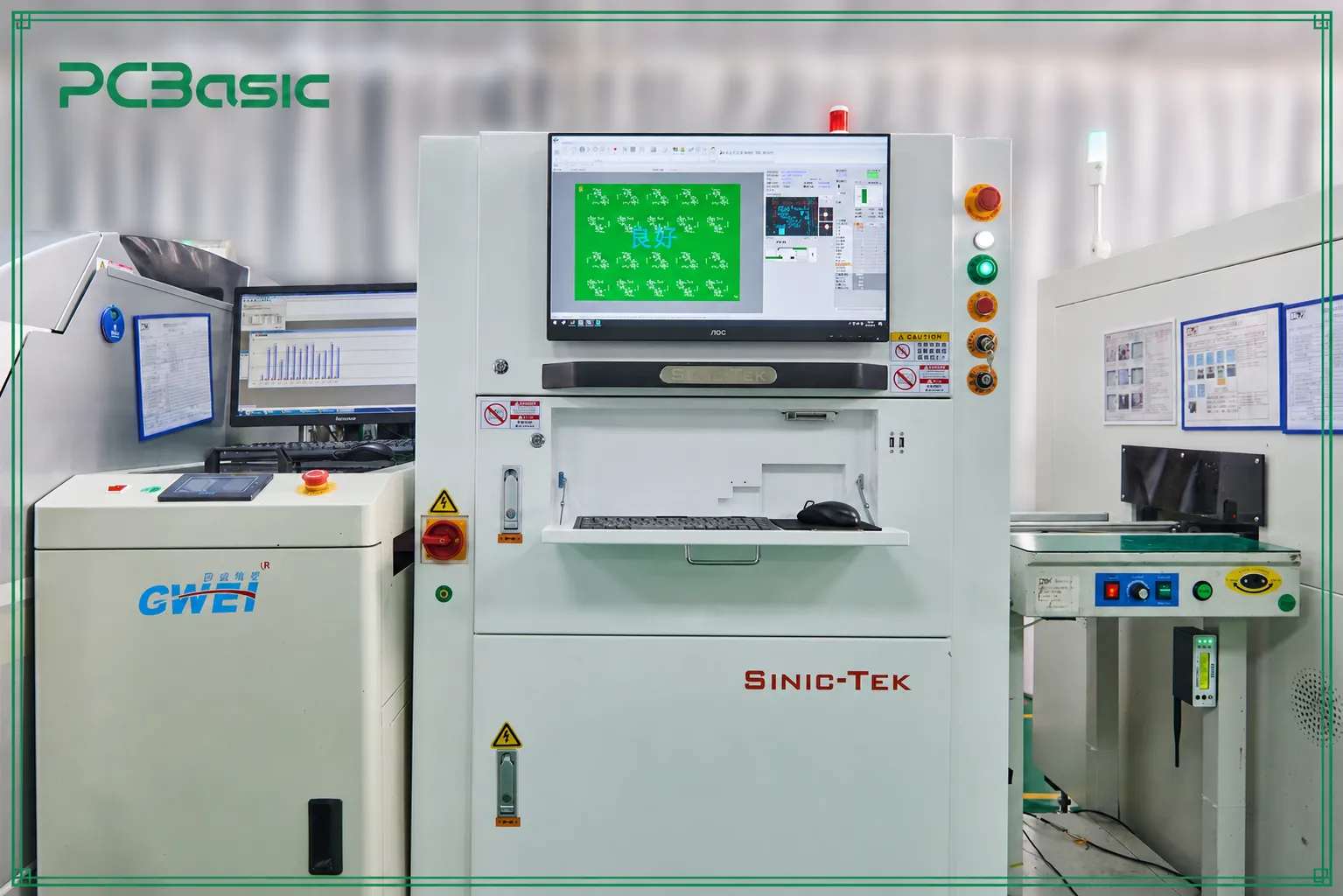
At PCBasic, these records are also viewed alongside the test results. After printing, use SPI to check whether the solder paste is uniform; after patch and reflow, use AOI to check the component position and surface solder joints; for components such as BGA that cannot see solder joints, use AOI to check the component position and surface solder joints; for components such as BGA that cannot see solder joints, use X-ray inspection as needed. This allows problems to be detected early and prevents the bad board from continuing into the subsequent process.
Inspection Should Separate SMT Checks From Electrical Testing
Inspection can only be done well when each process has a very clear task. Factories set up multiple inspections at all stages of production ——after all, it is impossible to find every defect in one quick inspection. The following table lists the inspection content of each checkpoint and its location in the SMT assembly process.
|
Checkpoint
|
What it checks
|
Why it matters
|
|
SPI
|
Solder paste volume, height, area, and deposit position
|
Catches print problems before components are placed
|
|
AOI
|
Visible component presence, position, orientation, polarity, and solder defects
|
Finds common SMT defects after reflow
|
|
X-ray
|
Hidden solder joints, voiding, and BGA-related risks
|
Inspects solder joints that cannot be seen from the surface
|
|
FAI
|
First completed board against BOM, placement, and approved files
|
Stops repeated errors before the batch continues
|
|
Electrical testing
|
Continuity, electrical behavior, or product-specific functions
|
Confirms whether the assembled PCBA works electrically
|
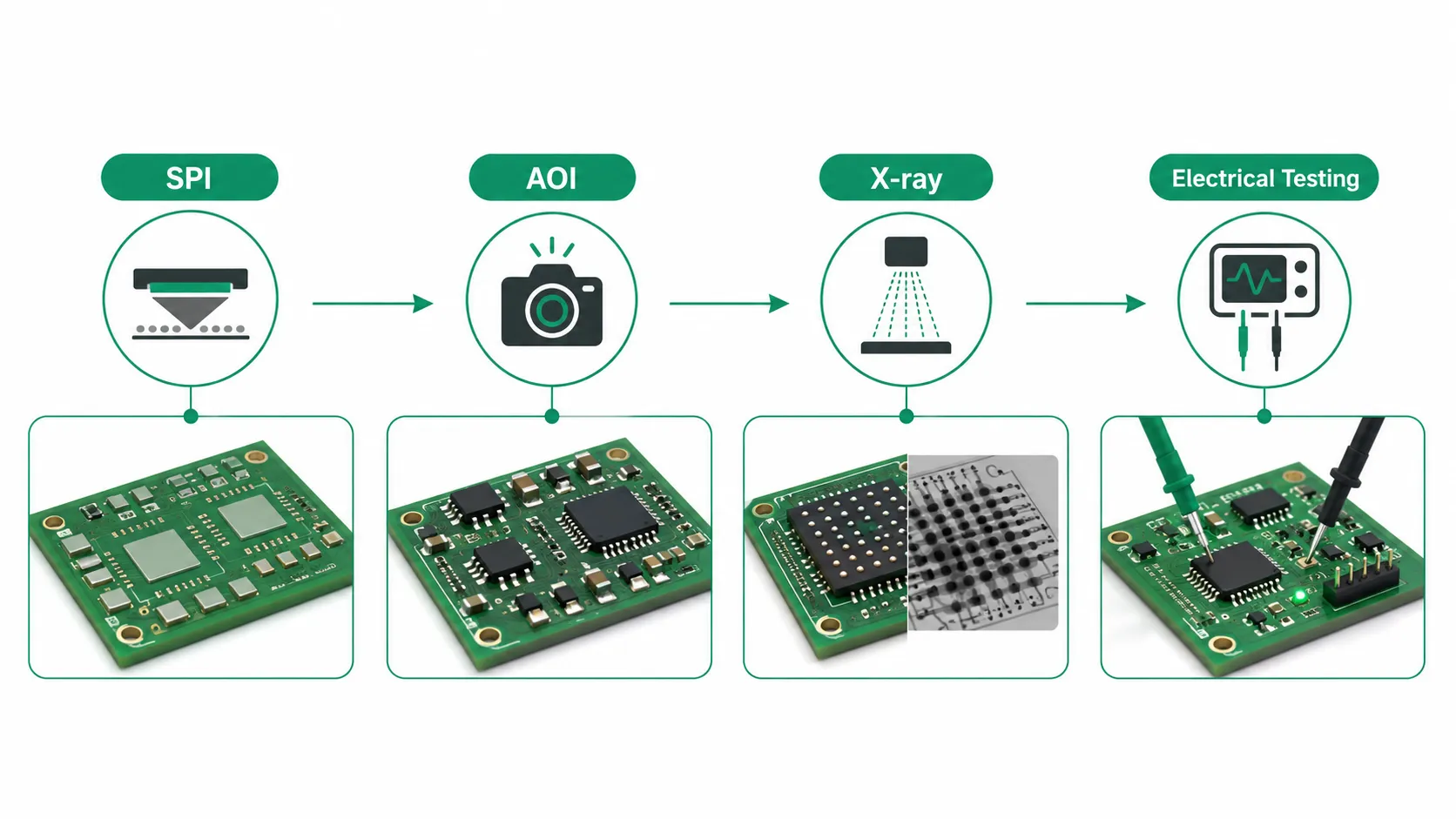
After assembly, a circuit board could seem perfect, but we still need to confirm that it works as planned. At that point, we introduce tests like as functional testing, flying probe testing, and in-circuit testing, depending on the project. AOI cannot accomplish this. It can see obvious soldering and placement mistakes, but it can't tell if the circuit works as it should. As a result, even if the board seems perfect after an AOI scan, PCBA electrical testing may still cause it to malfunction.
It can work the other way around too. Even if a board passes basic electrical testing, it may still require further processes like as programming, cable connection, enclosure installation, or validation under actual load circumstances.
At PCBasic, we do not run every test on every board. We first look at the board, the components, and the problems most likely to occur, then decide where SPI, AOI, X-ray, first article inspection, flying probe testing, or functional testing is actually needed. The aim is simple: catch problems as early as possible and make sure every result can be traced back to the right production batch.
Traceable Records Connect SMT, Testing, and Box Build
A single pass of a sample test does not mean that the process can be repeated stably. This is where production records come in handy. If there is a problem with a subsequent board, the team needs to know which batch of materials was used, which patch program was used, what was found during testing, whether it has been repaired, and which test results correspond to this board or batch.
Traceable records aren't just useful later when something goes wrong. From proofing to small batches and subsequent repeat orders, engineers can use these records to compare different batches. Without records, every time a problem is encountered, it must be checked from the beginning; with records, the next batch of production can first check the materials, processes, inspections and tests used before deciding whether adjustments are needed.
Traceability Helps Explain Defects Instead of Only Sorting Them
PCBasic has independently developed MES, IQC and First Article Inspection Systems, and combined them with CRM, ERP, IoT and ESD management tools to record and track key data in procurement, warehousing, production and inspection. This digital management system is used in two factories in Shenzhen and Huizhou at the same time. The total area of the two factories is about 20,000 square meters, focusing on small batch and mass production respectively.
In addition to internal systems, third-party certification is also a reference for judging the management capabilities of the factory. PCBasic has been certified by ISO 9001, ISO 13485, IATF 16949, ISO 14001, ISO 45001, UL and IPC Class 3.
Certification indicates that the factory has established corresponding management standards, and production records can further reflect whether these standards have been implemented. Whether materials, processes, inspections and tests are fully documented often provides a better understanding of how the factory is performed on a daily basis.
These records should not be interrupted after PCBA is completed. Many products still need to be fitted into the enclosure, connected cables, programmed with firmware, or work with displays, sensors, and other components. At this stage, the quality of the SMT in front is still important, but some issues only become apparent during assembly or final functional testing.
Many flaws are only apparent at the box-build stage. It is now necessary to verify that the PCBA can be installed into the device and that it will continue to operate as intended after installation.
Often, the outcome depends on a few crucial elements. Mounting holes, cable length, housing clearance, test point location, and connection orientation are a few examples. Insufficient heat dissipation space or cumbersome firmware operation will make subsequent assembly and testing more difficult.
Final functional testing is best planned before the housing design is finished. If the test fixture needs to contact buttons, interfaces, indicator lights or load points, it should be designed with a margin for the test position and operating space.
Because of this, just quoting the circuit board does not account for every risk involved in subsequent assembly. When requesting a quotation, it is best to specify which steps the project will take, what tests are required, whether the enclosure and cables are involved, whether the firmware is complete, and how it will be certified.
PCBasic PCBA production may link PCB assembly, component procurement, functional testing, and box build assembly for projects that go beyond board-level assembly rather of considering them as separate processes. This way, it is possible to match the needs ahead of time and lessen the instances in which the conditions are not met until much later.
When sending the PCB files and BOM, add the assembly notes, test needs, enclosure limitations, and expected build stage. This provides enough context for the PCBasic project review. The engineering and sourcing teams can examine the assembly path first, then calculate the price and lead time. Less details that are lacking. Later on, less adjustments.

Conclusion
SMT PCB assembly is not just a process of attaching components to the board. From document review, solder paste printing, mounting, and reflow soldering, to subsequent inspection, test record keeping, and final product preparation, every step has an impact on the next one. A small mistake in the previous step may lead to rework, rescheduling, or even the discovery of problems after the product is put into use.
True stability in production does not lie in the speed of a single piece of equipment or the individual excellence of a single process. The documents must match, the process must be stable, and the testing must be properly positioned. SPI, AOI, X-ray, first article inspection, flying probe testing and functional testing each address different issues. Records are also indispensable. When an anomaly occurs, the team can trace it back through the records; when the next batch is put into production, there is no need to re-experiment.
When comparing assembly suppliers, the quotation is of course important, but it should not be the only factor considered. The production control required for the project, the extent to which it needs to be achieved, whether testing and final assembly are necessary later, all these aspects should be clearly stated in advance. PCBasic can integrate PCB manufacturing, component procurement, PCB assembly, testing and final assembly, allowing the project to progress from board-level production to the final product.
FAQs
Q1: What is SMT PCB assembly?
A1: SMT PCB assembly is the process of mounting surface-mount components onto a PCB using solder paste, automated placement, reflow soldering, and inspection.
Q2: Is SMT inspection the same as functional testing?
A2: No. SPI, AOI, X-ray, and FAI verify different aspects of assembly and file conformity, while electrical testing checks circuit behavior and function.
Q3: When should the box build requirement be discussed?
A3: They should be discussed before enclosure, cable, firmware, and final testing decisions are finalized.