
Global high-mix volume high-speed PCBA manufacturer
9:00 -18:00, Mon. - Fri. (GMT+8)
9:00 -12:00, Sat. (GMT+8)
(Except Chinese public holidays)





HomePage > Blog > Knowledge Base > TPMS PCB Assembly: Building Reliable Electronics Inside a Tire
1. What Actually Goes on a TPMS PCBA?
2. Why TPMS Sensor PCB Assembly Is Harder Than Its Size Suggests
3. From Bare Board and BOM to Finished TPMS PCB Assembly
4. TPMS Testing Has to Go Beyond Visual Inspection
5. Moving TPMS PCBA from Prototype to Production
About the size of a coin, every tire in
modern-day vehicles is fitted with a small PCB, which senses pressure and
temperature, while enduring centrifugal forces capable of destroying any normal
electronics in a few seconds. The endurance of the TPMS PCB assembly allows all
this function to be performed in such a small area.
Tire pressure monitoring has become compulsory in many new vehicles for more than a decade in many developed countries. Thus, TPMS PCBA has emerged from a mere automotive accessory to a high volume and safety-related product.
The failure of a single sensor can result in a TPMS malfunction warning and may prevent accurate pressure information from reaching the driver, potentially leaving a pressure loss undetected. This safety link is exactly what makes the PCBA systems used in the tire pressure monitoring systems so different in their role and stakes from most of the consumer electronics.
This article provides insight into what components make up the TPMS sensor PCB assembly, why creating one is more difficult than it may seem at first glance, how a manufacturer transforms a circuit board design to an actual working part, and what tests must be done for that component to even leave the factory.
Anyone sourcing a TPMS sensor PCBA program should come away from this article with a clearer sense of what separates a supplier who understands automotive-grade demands from one who only assembles consumer boards.
A TPMS PCBA looks deceptively simple from the outside, but it packs several distinct functional blocks onto one small, rigid board.
The MEMS Pressure Sensor lies at the core of each tire pressure sensor, acting as the mechanism that changes the pressure to an electrical signal that is further conditioned by the front-end circuit on the board.
Temperature sensing accompanies pressure sensing because temperature compensation is required when measuring the tire pressure as well as the electrical characteristics of the tire pressure sensor. Otherwise, the tire pressure sensor may report an inaccurate pressure reading as the tire got warm from driving on the highway.

The low-power microcontroller analyzes the data from sensors and takes care of the sleep and wake-up cycle which makes it possible to work on the battery for many years within a sealed tire.
The RF transmitter together with the small antenna transmits the information about the pressure to the vehicle's receiver; the power circuit controls the sensor battery supply under changing temperature conditions. All of them have to function throughout the whole lifetime of the battery because replacement of the TPMS sensor typically involves its full replacement.
|
Functional Block |
Role on the Board |
Key Design Constraint |
|
Pressure sensor |
Converts tire pressure into electrical signal |
Accuracy across wide temperature range |
|
MCU |
Processes data, manages power states |
Ultra-low sleep current |
|
RF transmitter + antenna |
Sends readings to vehicle receiver |
Range through wheel and tire material |
|
Power management |
Regulates battery output |
Survives years without replacement |
Every constraint that makes a TPMS sensor small also makes TPMS sensor PCB assembly considerably harder than typical automotive PCB assembly work.
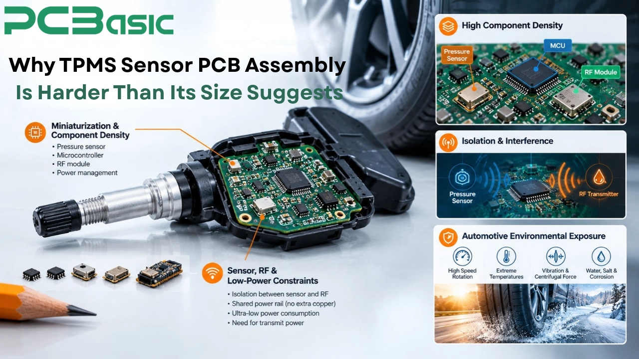
Integrating a pressure sensor, microcontroller, RF module, and power management system onto a single board in a valve stem or wheel well is a tough challenge in terms of placement accuracy.
This high component density implies that if even one component is misaligned during reflow, it can lead to solder bridging or other assembly defects. There is not much chance for layout changes on a compact board because additional routing or component spacing requires available PCB area.
Careful isolation may be required between the pressure-sensing circuitry and the noise produced by the RF transmitter. However, the two functions need to coexist on a compact board with limited space for routing and shielding. The battery life considerations force all design decisions towards reduced current consumption, but this opposes the requirement for transmit power in the RF part of the system.
A TPMS board rotates with the wheel at highway speeds, is subjected to centrifugal forces of over a hundred times gravity, and switches between hot summer asphalt and cold winter temperatures, all while being sealed within an enclosure that is subjected to corrosive salts, water, and vibration.
Automotive PCB assembly in cabin electronics may encounter less severe mechanical and thermal stress than a wheel-mounted TPMS board. The dashboard module resides in a controlled and safe environment, while the TPMS sensor does not have that luxury for even one mile of its operation.
Turning a TPMS design into a manufacturable product starts long before any component touches the board.
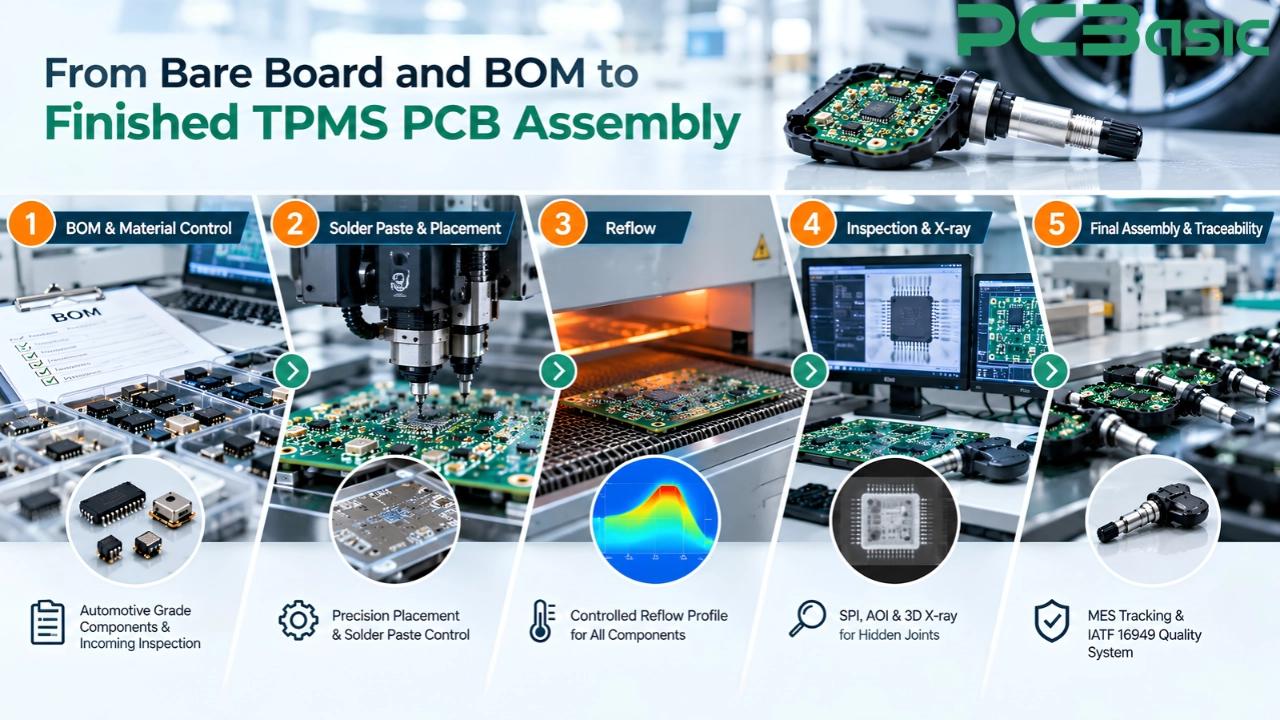
When checking bills of material for a TPMS sensor PCBA, it is critical to verify that the specified components meet the required automotive ratings. A consumer-grade MEMS sensor or MCU with a lesser temperature range will not function reliably under the required operating conditions.
Incoming material inspections help ensure counterfeit or out-of-spec components do not make it to the production line. This is tremendously important because even one incorrect or out-of-spec component can affect the performance of a compact TPMS board.
Solder paste volume control matters intensely on a board this dense, since even a small excess can bridge adjacent pads on fine-pitch components packed close together.
During reflow profile creation it is crucial to take into account the thermal tolerance of every component at once, balancing the sensitivity of the pressure sensor with the larger thermal mass of the power system. If it is done wrong, the results could be improperly formed solder joints or thermal damage to temperature-sensitive components during reflow.
PCBasic can perform SPI and AOI inspections during TPMS PCB assembly, in order to detect issues regarding solder paste deposition and placement of components; however, the use of 3D X-ray is done on hidden joints where required.
Identifying any flaw in this stage will cost much less compared to identifying it as a field return after several months once the vehicle has shipped. Traceability of materials and MES process control are used to link any completed tire pressure monitoring system PCB assembly to its lot information. All these can be carried out under the IATF 16949 quality management system for applicable automotive projects.
A board that looks perfect under a microscope can still fail the moment it needs to transmit a signal through a spinning wheel.
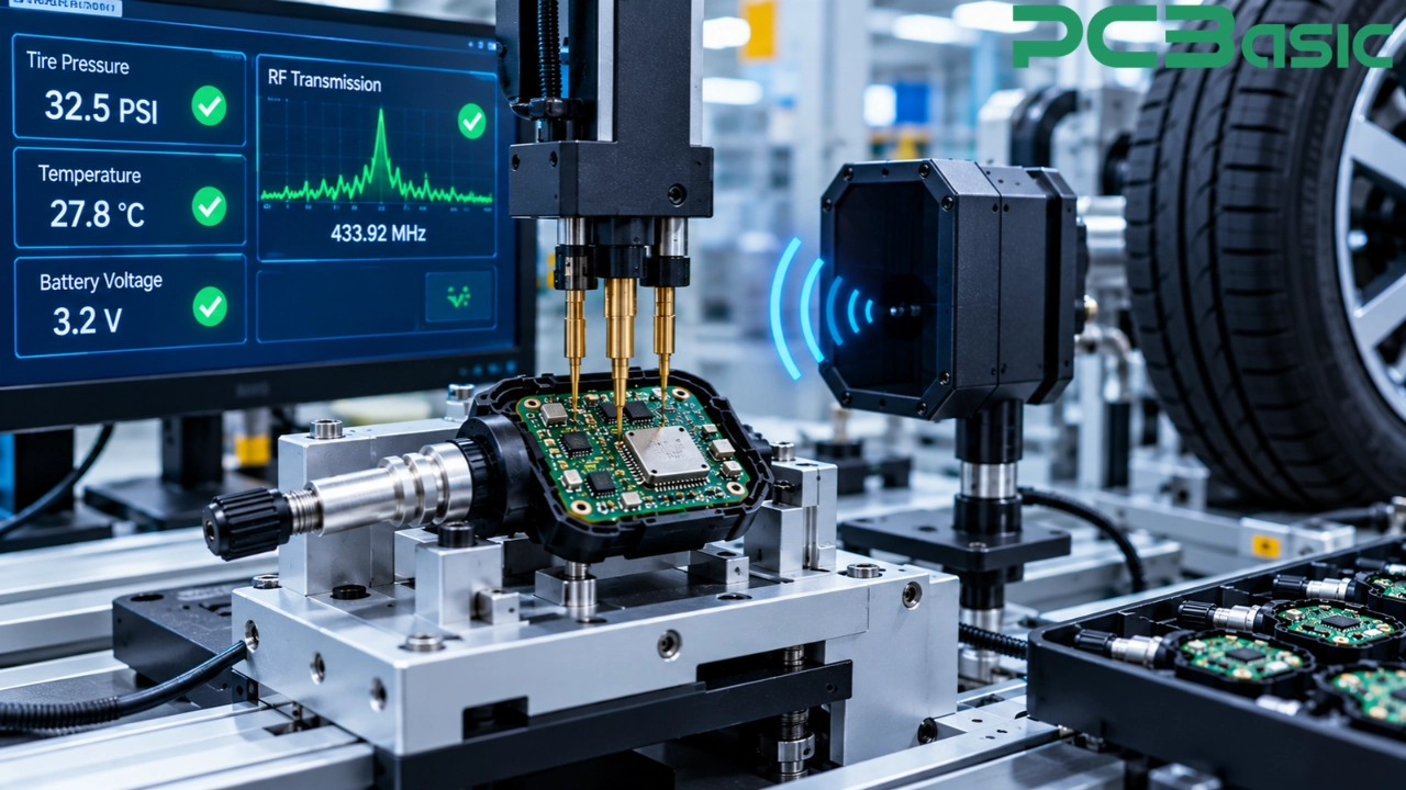
The in-circuit test helps verify that the tested connections and components on the TPMS PCBA conform to their specifications, allowing certain electrical defects to be detected far ahead of time before the PCBA undergoes further testing. This step validates that the board has been manufactured properly, but not necessarily that it operates properly in practice. A board may meet all electrical requirements in the lab but fail in practice.
TPMS testing may verify that the pressure sensor gives an accurate reading at defined test points, that the RF transmission operates as specified, and that the power management properly transitions the board between the required operating modes.
An electrical test pass but not having a wake-up function after going into sleep mode makes the sensor just as useless as having a poor solder joint because the driver does not have the pressure data at the critical time.
Standard production TPMS testing ensures that every unit manufactured conforms to the specifications before shipment, while automotive qualification testing verifies whether the design is qualified based on the standards related to temperature cycling, vibration, and centrifugal force. Both may be required depending on the product and customer requirements because qualification testing will show whether the design meets specified requirements while production testing will show whether the individual parts have been manufactured properly.

The presence of a few prototype assemblies does not give much indication as to how the TPMS PCB assembly design will perform during large-scale production.
Even minor changes in the amount of solder paste deposited on a component, as well as minor inconsistencies in the reflow process between the panels, can change a design that is marginally good into one that is bad when production scales up.
Units produced in a pilot program, where testing is conducted according to the product requirements, may uncover potential issues that might not be uncovered by a small number of prototypes.
PCBasic is able to handle the TPMS program for prototype builds all the way up to automotive volume build of PCB assembly using the same standard of incoming inspection, process control, and traceability for all stages instead of considering prototype builds as a separate discipline process.
The success or failure of a TPMS PCB assembly lies in decisions made far before any sensor turns within a tire, namely the parts used, heat management, radio frequency design, and testing that correlates with the stresses the board will experience.
Accurate reporting of tire pressure over the sensor's intended service life is dependent in part on a PCBA manufacturer that regards each of these as an element of safety, rather than just another PCB assembly in automotive electronics.
When it comes to finding a manufacturing partner that recognizes the special requirements of this PCB, PCBasic is here to help.
Q1: What is TPMS PCB assembly?
It is the manufacturing of the small PCBs contained within the TPMS sensor, integrating pressure sensing, a microcontroller, RF communication, and power management onto one single board.
Q2: Why is TPMS sensor PCB assembly harder than typical automotive PCB assembly?
The combination of extreme miniaturization, centrifugal forces, wide temperature swings, and conflicting low-power versus RF-range requirements creates constraints that can be particularly challenging for compact automotive boards.
Q3: What does TPMS testing check beyond basic electrical function?
TPMS testing is performed for pressure accuracy through the complete range of the sensor, RF transmission through a simulated tire and wheel environment, and proper power cycling, along with regular in-circuit electrical testing.
Q4: How does automotive qualification differ from standard production testing?
Qualification testing proves that the product is able to cope with automobile stress factors such as vibrations and centrifugal forces, whereas production testing proves that the finished product meets specifications.
Q5: What should change when a TPMS design moves from prototype to full production?
Expect closer attention to solder paste consistency, incoming material control, and a pilot run appropriately sized to help reveal process variation that may not appear in a small prototype batch.

Assembly Enquiry
Instant Quote



Phone contact

+86-755-27218592
In addition, we've prepared a Help Center. We recommend checking it before reaching out, as your question and its answer may already be clearly explained there.
Wechat Support

In addition, we've prepared a Help Center. We recommend checking it before reaching out, as your question and its answer may already be clearly explained there.
WhatsApp Support

In addition, we've prepared a Help Center. We recommend checking it before reaching out, as your question and its answer may already be clearly explained there.
