
Global high-mix volume high-speed PCBA manufacturer
9:00 -18:00, Mon. - Fri. (GMT+8)
9:00 -12:00, Sat. (GMT+8)
(Except Chinese public holidays)





HomePage > Blog > Knowledge Base > IoT GPS Module PCB Assembly Service: From Positioning to Data Upload
1. Key Components of an IoT GPS Board
2. Key Considerations for GPS Module PCB Assembly
3. Testing IoT GPS Boards After Assembly
4. What Does an IoT GPS Module PCB Assembly Service Include?
For instance, in the serial port logs, you can already see the new coordinates output by the GPS module. However, the location on the dashboard map has not been updated yet. At this point, it is necessary to check separately whether the controller read the coordinates, whether the board established a data connection, and whether the server received the update.
If you’re using an IoT GPS module PCB assembly service for a custom board, this article will explain what to check during the assembly process and how to verify each step from the first location fix to server receipt.
At the heart of the positioning stage is the satellite receiver—either a GNSS receiver IC with external components or a castellated or LGA (Land Grid Array) module that may support multiple constellations, such as GPS, GLONASS, Galileo, and BeiDou.
Depending on the enclosure and module requirements, the board may use an onboard ceramic chip antenna, a helical antenna, or a coaxial connector (such as U.FL/IPEX or SMA) for an external GNSS antenna.
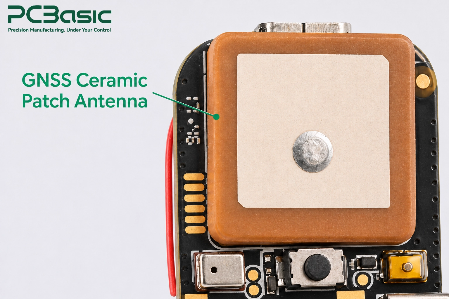
Many GPS IoT module PCBA designs pair the GNSS receiver with a low-power host microcontroller (such as an Arm Cortex-M series MCU) that parses NMEA or UBX messages, can apply motion filtering, and manages sleep states.
To send telemetry, the board integrates a wireless communication interface such as an LTE-M or NB-IoT modem, a LoRaWAN transceiver, or a BLE/Wi-Fi combo chip. LoRaWAN devices send data through a gateway, while designs using BLE for uplink can relay data through a connected phone or gateway. In compact GPS tracker PCB assembly, the GNSS and cellular transmit antennas can sit just millimeters apart. Antenna placement and shielding help protect the satellite receiver from interference during cellular transmission.
Battery-powered trackers can spend long periods in deep sleep and then draw substantially more current when they wake to acquire a fix and transmit data. Supporting this load profile may involve:
• Power management ICs (PMICs), low-dropout regulators (LDOs), and buck/boost converters, as needed, to maintain stable supply rails.
• Bulk and local decoupling capacitors placed near the cellular modem’s supply pins according to its hardware design guide to help limit voltage dips during transmission.

Executing GPS module PCB assembly reliably requires translating RF and power-integrity rules into concrete shop-floor controls.
GNSS and cellular modules often use bottom-terminated LGA packages or castellated pads. Some also have a large central ground or thermal pad. If too much solder paste is printed onto that center pad, the module can float during reflow, tilting the package and leaving perimeter connections open.
Before production, check the module orientation against the assembly drawing and, if the module has a center pad, review the stencil apertures for the center pad against the module supplier’s recommendations.
Mechanical and RF transitions are frequent points of failure in GNSS module PCB assembly:
• Coaxial connectors (U.FL/IPEX): Check that the receptacle sits squarely on its footprint. During final assembly, align the cable plug with the receptacle and mate them according to the connector manufacturer’s instructions.
• Ceramic chip antennas: Verify the part orientation against the assembly drawing and check the copper keep-out against the antenna manufacturer’s layout requirements.
High-current battery connectors endure repeated mechanical stress during assembly, testing, and field battery swaps. Check connector seating and orientation against the assembly drawing, then inspect the solder joints at the terminals and any mechanical anchor tabs.
On the digital side, engineers should expose the required programming and debug interfaces via accessible test pads, such as SWD or JTAG for programming and debugging, or UART TX/RX for serial logs or bootloader-based programming where supported. On the first assembled board, confirm that the fixture probes contact the intended pads and that the programming tool can communicate with the target device.
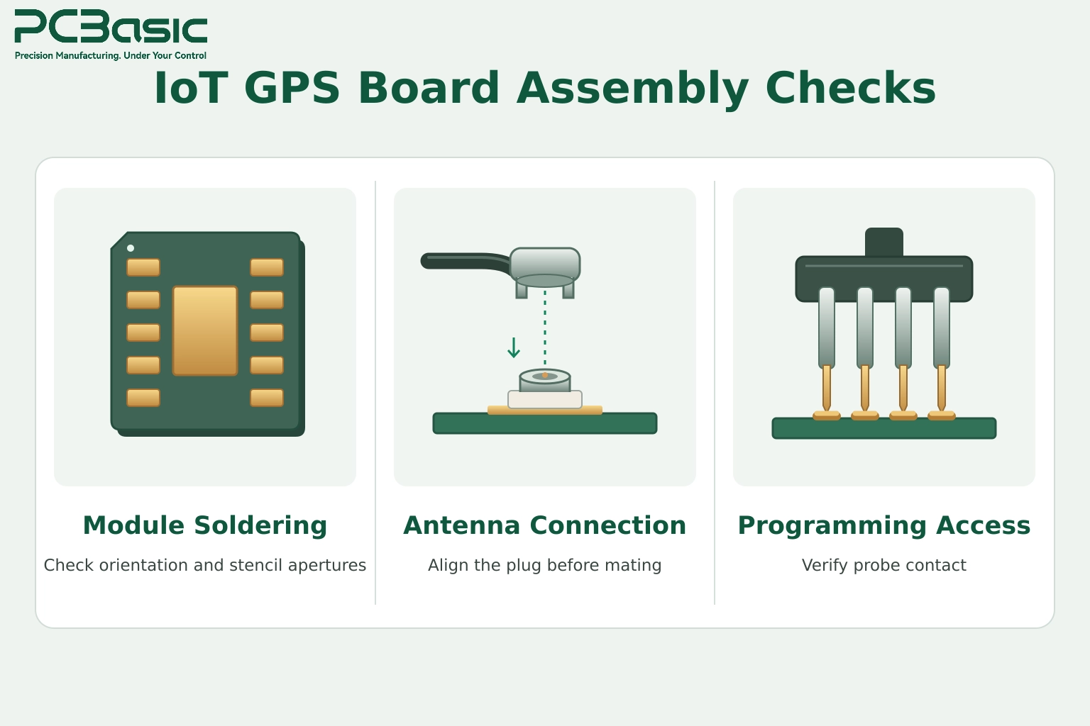
In professional IoT GPS PCB assembly, verification moves step by step from solder joint inspection to confirming that the server received the expected data.
• 3D SPI (Solder Paste Inspection) checks paste volume, height, and registration before component placement.
• AOI (Automated Optical Inspection) checks component presence, orientation, polarity, and visible solder joints after reflow.
• X-ray inspection can help assess hidden solder joints beneath LGA modules when the inspection plan calls for it.
Once structural checks pass, technicians perform a current-limited power-up to verify rail voltages and check that the board’s current draw is within the expected range for its initial power-up state before flashing firmware.
With test or production firmware loaded onto the host MCU, verify that the controller can read and use the positioning data. If live satellite reception is unreliable at the test station, the agreed test setup may include a GNSS simulator or, where permitted, a GNSS repeater.
Technicians or automated test scripts monitor the MCU’s UART or USB debug interface to confirm that:
1. The GNSS module initializes and communicates at the expected baud rate.
2. The controller reads location data from a valid fix.
3. The board acquires a fix within the agreed time-to-first-fix (TTFF) window under the defined test conditions.
Using a provisioned test SIM/eSIM, a cellular board registers on the network, establishes a data connection, and attempts to send a formatted payload to a test MQTT broker or an HTTPS endpoint, depending on the project.
Record three separate results for each unit: valid position data at the controller, network connectivity, and receipt of the correct payload at the endpoint. For the first, capture the coordinates and fix timestamp from the controller log. For the second, record the modem’s registration status and verify that the board has established a data connection. For the third, compare the device ID, timestamp, and coordinates in the received message with the values recorded on the board. Use the receiving application’s log to confirm receipt, since a local “send successful” message may only mean the payload was handed to the modem or queued for transmission, depending on how the firmware reports send status.
For example, if the board logs a fresh fix but the dashboard still shows yesterday’s position, check the modem log for registration and data connectivity. If those checks pass, compare the device’s upload log with the receiving application’s log to see whether the message arrived and whether it was associated with the correct device. If the application received the correct update, check whether it used that update to refresh the device’s location on the dashboard.

For battery-powered trackers, functional testing routines often cycle the board through a short operating sequence: sending an initial packet, commanding the MCU and radios into deep sleep, verifying that sleep current drops into the specified range, and then triggering a wake-up event to confirm that the server receives a second location update.
When comparing quotes for GPS module PCB assembly services, clarify who supplies the components, which tests are included, and what records will accompany the shipment.
• Full Turnkey: The assembly partner procures the bare PCBs, GNSS and cellular modules, passives, connectors, and mechanical shields.
• Consigned (Customer-Supplied): Your team purchases and ships the components to the factory for assembly and inspection.
• Partial Turnkey (Combo): For GPS tracker PCBA projects, your team can supply long-lead modules or specialized antennas while the assembler sources standard passives and power ICs.
Whichever model you choose, make sure the Bill of Materials (BOM) or sourcing agreement specifies who supplies items such as U.FL coaxial pigtails, SIM card trays, and shielding lids.
Specify whether the manufacturer should flash production firmware, load and run diagnostic firmware, or do both. If your build requires multi-stage testing, document the programming sequence, pass/fail thresholds, and cycle-time budget upfront.
For upload verification, agree on who provides the firmware, fixture, test SIM or network access, and staging endpoint. Define how the factory will capture proof that the endpoint received the expected data.
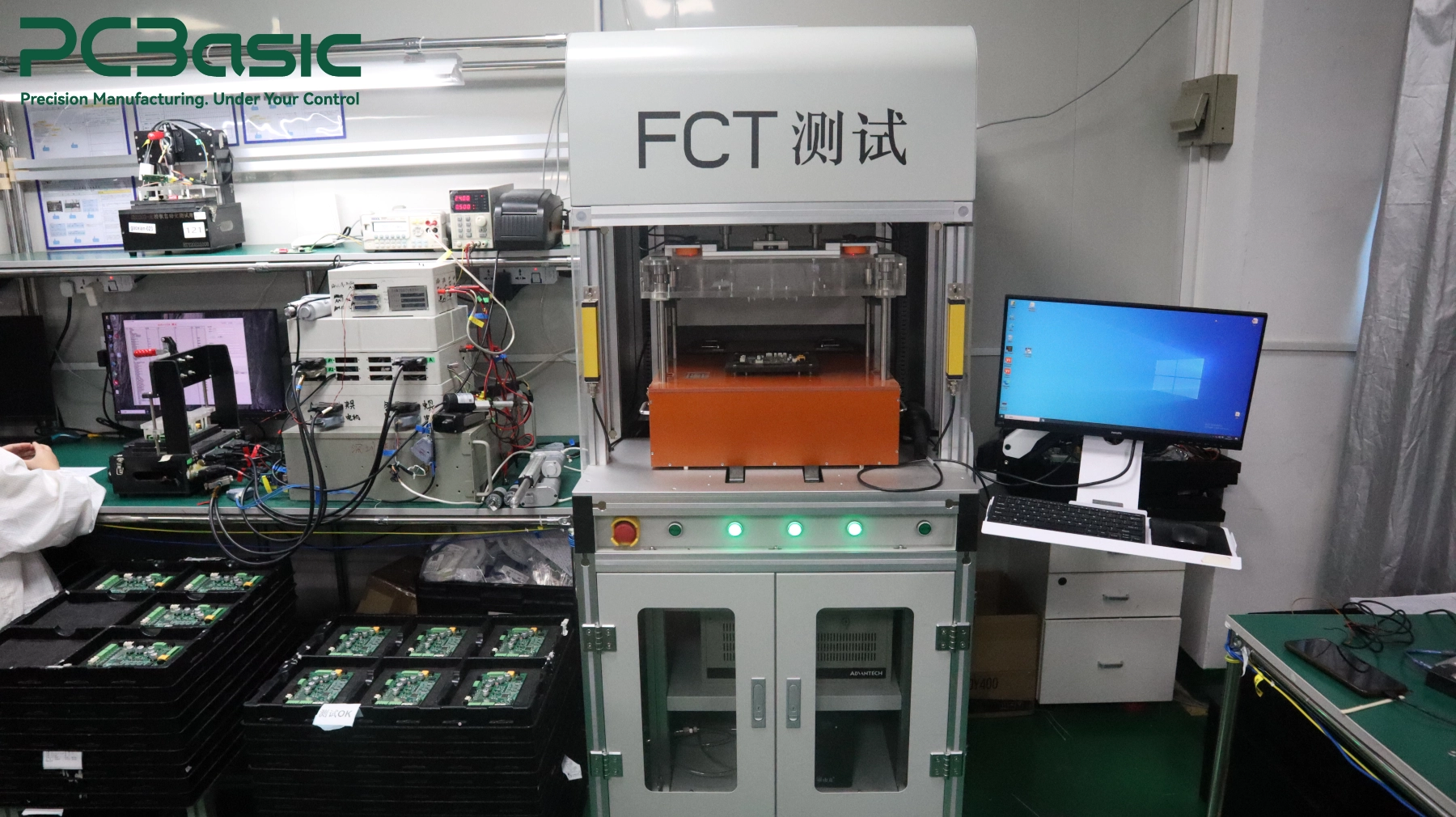
• Bare assembled PCBA: Populated and inspected boards ready for your team to program and integrate.
• Programmed and tested PCBA: Boards flashed with production firmware and verified against agreed power, positioning, and connectivity criteria, including server receipt when upload testing is in scope.
• Fully integrated box-build: Assembled boards mounted in enclosures with antennas routed and batteries connected, as specified in the build scope.
PCBasic can assemble the customer-designed board and, when included in the project scope, flash customer-supplied firmware and carry out agreed functional tests. Define which inspection and test records should be tied to board serial numbers or production lots so results can be traced after shipment.
Verify location acquisition, network connectivity, and data receipt at the endpoint as separate checkpoints before releasing an IoT tracking board. Agree on the test conditions, pass/fail criteria, and manufacturing scope before production. Contact PCBasic with your board files and test requirements to confirm the scope for assembly, programming, and upload verification.
Q1: Does a GPS module upload location data on its own?
A standalone GPS/GNSS receiver provides positioning data to a host controller. Uploading that data requires a communication interface and firmware that sends the payload to a receiving endpoint. Some combined modules integrate both positioning and cellular communication.
Q2: Does the assembly service include firmware programming and upload testing?
Firmware programming and upload testing are included when specified in the agreed project scope. Provide the compiled firmware and test procedure, and confirm who will supply the fixture, network access, and endpoint needed to verify receipt.
Q3: Why can an IoT GPS board obtain a location but fail to upload it?
A valid fix confirms that the GNSS receiver calculated a position. Upload can still fail if the controller did not read the fix, the modem did not establish a data connection, the device could not reach or authenticate with the endpoint, or the receiving system rejected the payload. Check the controller, modem, and endpoint logs in that order to find where the data stopped.

Assembly Enquiry
Instant Quote


Phone contact

+86-755-27218592
In addition, we've prepared a Help Center. We recommend checking it before reaching out, as your question and its answer may already be clearly explained there.
Wechat Support

In addition, we've prepared a Help Center. We recommend checking it before reaching out, as your question and its answer may already be clearly explained there.
WhatsApp Support

In addition, we've prepared a Help Center. We recommend checking it before reaching out, as your question and its answer may already be clearly explained there.
