Global high-mix volume high-speed PCBA manufacturer
9:00 -18:00, Mon. - Fri. (GMT+8)
9:00 -12:00, Sat. (GMT+8)
(Except Chinese public holidays)
Global high-mix volume high-speed PCBA manufacturer
9:00 -18:00, Mon. - Fri. (GMT+8)
9:00 -12:00, Sat. (GMT+8)
(Except Chinese public holidays)
HomePage > Blog > Knowledge Base > Heavy Copper PCBs: A Comprehensive Guide
With advancements in social science and household technology equipment, user expectations for electronic product reliability have been on the rise. Consumers now expect their products to have superior thermal conductivity, higher voltage tolerance, and enhanced performance in extreme operating conditions. Notably, heavy copper PCBs meet these user expectations, making them an important part of 5G service stations, aerospace, and military applications.
As EV manufacturing and industrial automation industries grow, manufacturers of these products have large demands for circuit boards that can handle high power densities and intense heat generation.

Given the critical nature of these components, these PCBs have shown a promising solution, ensuring higher efficiency, less maintenance, and resistance to failure. This article will examine what thick copper PCBs are, their applications, as well as design considerations for preventing common issues during their development.
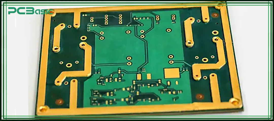
This is a circuit board made of multi-layer structures and thicker copper traces than those found in ordinary household PCBs. While traditional printed boards use copper layers of around 1 oz/ft², thick copper PCBs start at 3 oz/ft² and can reach up to 20 oz/ft² or more.
In modern electrical circuits, appropriate copper PCB thickness provides:
● Higher current handling capacity
● Lower electrical resistance
● Reduced voltage drop along trace paths
● Lower impedance
● Minimal signal loss and distortion
Use these PCBs in applications that require mechanical strength, high power density, and durability in harsh conditions.
Also, they strengthen the electrical circuit layers in systems that require proper heat management, such as EV circuits.
 About PCBasic
Time is money in your projects – and PCBasic gets it. PCBasic is a PCB assembly company that delivers fast, flawless results every time. Our comprehensive PCB assembly services include expert engineering support at every step, ensuring top quality in every board. As a leading PCB assembly manufacturer, we provide a one-stop solution that streamlines your supply chain. Partner with our advanced PCB prototype factory for quick turnarounds and superior results you can trust.
These PCBs create a low-resistance pathway for currents in devices that consume too much power. This increases efficiency and reduces the risk of burnout. For instance, a PCB with a 3oz copper thickness can carry currents of 10 to 20 amps over a 10-year period. Meanwhile, it carries over 50 amps in applications with a 10-oz thickness.
Similarly, they are durable and offer superb mechanical strength during operation, resisting stresses like bending or vibration.
In terms of cost, they reduce the number of repairs and replacements in remote-based infrastructures, such as wind turbines and off-grid solar power systems, where maintenance is time-consuming and expensive.
Furthermore, thick copper PCBs allow engineers to build advanced electrical circuits on a single board without affecting current carrying performance. This supports the manufacture of small-sized systems, compared to standard PCBs that require extra materials to deliver the same power.
They are used in the automobile industry in EV Battery Management Systems (BMS). These systems rely on thick copper PCBs to deliver power. Their copper trace composition provides a low-resistance path that prevents overheating issues when current passes through them.

Also, in renewable energy applications like solar inverters, the PCB regulates the conversion of solar energy into usable AC power. At the same time, it efficiently controls the storage capacitors in wind turbines to prevent unwanted heat buildup.
In data centers and 5G base stations, heavy copper PCBs enable the system to provide an uninterrupted power supply, addressing the heat generation issues in high-frequency signal transmissions. Military and aerospace equipment also benefits, as these PCBs safely control the rheostats and resistors used in the circuit.
Heavy copper PCBs are also found in medical devices. They provide stable power distribution in equipment like defibrillators or MRI machines.
Additionally, they are employed in autonomous vehicle (AV) systems to power the navigation and computer dashboards.
Factors such as trace width, copper PCB thickness, and substrate material directly affect the effectiveness of thicker printed boards.
Choosing the appropriate copper thickness and trace width is important in PCB design. These allow engineers to choose thicknesses that safely handle the required current loads without causing excessive heat buildup. Selecting a copper thickness between 3oz to 20oz is advisable during development, as wider trace widths carry more current with less resistance.

In the same vein, designers must follow the IPC-2221 standard when calculating trace thickness and widths.
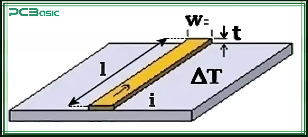
According to IPC-2221, trace width (W) can be calculated for a given current (I) and acceptable temperature rise (ΔT) using the following formula for external traces:

Where:
● I is the current in amperes,
● ΔT is the temperature rise in °C
● K is a constant that depends on the trace location (e.g., 0.048 for internal and 0.024 for external layers).
● The exponent 1/0.725 (approximately 1.38) accounts for the non-linear relationship between trace width and temperature rise.
For example, if the external copper traces on a PCB are required to carry 8 amps of current with a maximum temperature rise of 20°C, then we can calculate the width (W) as follows:

Assuming K = 0.048

W = 85.11
Based on the calculation above, the width of the trace is 85.11mm
The substrate is the board's foundation, providing mechanical support and insulating the copper layers. During the design, raw materials like 'FR-4', with an operating temperature of 130°C, should be used for creating the printed board. But regulators also suggest the use of materials with higher glass transition temperatures (Tg), like polyimide and ceramic substrates that withstand repeated thermal cycles without losing strength.
Moreover, engineers must choose substrate materials with thermal expansion coefficients that are similar to that of copper so as to reduce mechanical stress and prevent cracking, a major factor in materials used in high-temperature applications.
When electric current flows through 'copper traces' in a circuit board, its internal resistance generates heat, leaving the circuit through convection. As such, technicians must design copper PCB thicknesses that can carry the maximum expected current without exceeding the acceptable temperature rise.
During development, engineers should use Finite Element Analysis (FEA) simulations to predict the temperature distribution around the trace layouts. This approach improves thermal efficiency and maximizes the safety margin in such systems.
To manage heat variations in PCB design, designers should focus on techniques that will keep the copper boards reliable, cool, and long-lasting. Start with thermal vias and active cooling solutions, such as micro fans, to create conductive paths that quickly transfer heat between system layers.
Engineers should also add heat sinks to primary components and use graphite—or silicone-based heat pads to aid heat transfer across the circuit surfaces.
When designing these heavy printed boards, adopt environmentally friendly sustainable practices to minimize environmental damage. First, manufacturers should use copper recycling systems to manage copper waste efficiently. Likewise, select materials from suppliers with good recycling processes.
In addition, manufacturers should leverage cleaner etching and plating processes by using non-toxic chemicals, such as low-acid or non-ammonia solutions, to lower toxic waste.
For substrate materials, designers can choose from environmentally sustainable alternatives, like bio-based laminates, which lessen the dependence on fossil fuels.
After manufacturing, choose finishes that are free from lead or other toxic compounds. For example, surface finishes like Electroless Nickel Immersion Gold (ENIG) offer durability and good electrical conductivity without introducing harmful heavy metals.
There are structural differences between heavy and ordinary copper PCBs, particularly in copper weight, manufacturing processes, and thermal properties.
|
Feature |
Ordinary Copper PCB |
Heavy Copper PCB |
|
Manufacturing Process |
It requires a straightforward process with standard copper foils (usually 1 oz/ft²) laminated and etched with basic chemical processes. |
They require specialized etching and plating techniques, and more complex fabrication methods.
|
|
Copper Weight |
The copper thickness ranges from 0.5 oz/ft² to 1 oz/ft². |
The thickness ranges from 3 oz/ft² to 20 oz/ft² or more. |
|
Inner Layer Copper |
They have thin copper layers, similar in thickness to the outer layers. |
It is designed with thick copper PCBs.
They support higher current loads but typically carry about 50% of the outer layer's current.
|
|
External Copper |
It has thinner external copper layers that handle moderate current distribution. |
They are made of thicker copper layers that can withstand larger load currents. |
Aside from these differences, heavy copper PCBs offer sustainability benefits because of their extended lifespan and lower replacement needs. However, the manufacturing process has a higher environmental impact due to chemicals and copper waste.
Heavy copper PCBs have contributed positively to the electronic industries by addressing the drawbacks found in ordinary circuit boards that fail when handling high currents. They prolong the lifespan of electronic components and effectively handle the heat generated by the system.
The design comprises copper traces that show minimal resistance when connected to high-current equipment.
With this magnitude of characteristics that thick copper PCB offers, consider utilizing them in your next project.

Assembly Enquiry
Instant Quote
Phone contact

+86-755-27218592
In addition, we've prepared a Help Center. We recommend checking it before reaching out, as your question and its answer may already be clearly explained there.
Wechat Support

In addition, we've prepared a Help Center. We recommend checking it before reaching out, as your question and its answer may already be clearly explained there.
WhatsApp Support

In addition, we've prepared a Help Center. We recommend checking it before reaching out, as your question and its answer may already be clearly explained there.
