
Global high-mix volume high-speed PCBA manufacturer
9:00 -18:00, Mon. - Fri. (GMT+8)
9:00 -12:00, Sat. (GMT+8)
(Except Chinese public holidays)





HomePage > Blog > Knowledge Base > Drone GPS Module PCBA: How Design, Assembly, and Testing Affect GNSS Reliability
Table of Contents
1. Inside a Drone GPS Module: How GNSS Signals Become Navigation Data
2. Why Drone GPS Modules Are Especially Sensitive to RF Noise and Integration
3. Turning GPS PCB Design Into a Reliable PCBA
4. Why Inspection Alone Cannot Verify GPS Navigation Performance
5. From a Working Prototype to Repeatable GPS Module Production
A drone slightly drifting from the flight path
during a mapping survey does not only mean wasted time — it may make a good
survey dataset obsolete. And reliable UAV positioning depends in part on a
compact drone GPS module PCBA that can maintain stable GNSS reception despite
vibration, electromagnetic interference, and changing flight attitudes.
The demand for this type of technology is only going up. According to industry research, the size of the global UAV navigation systems market in 2026 will be estimated at $13.93 billion and will reach $27.3 billion by 2030, mainly due to GNSS positioning becoming standard equipment of commercial and industrial drones. This article explains how a GPS circuit board processes raw satellite data to give you a stabilized position fix, why the circuitry differs from a regular controller PCBA and what you need to do to transition from a functional prototype to GPS module PCB assembly at scale.
Before we explore the trade-offs that designers make or how an antenna is assembled, it is important to know what occurs from when the satellite signal hits the antenna to when a flight controller gets coordinates.
The GNSS antenna receives very weak signals transmitted from satellites orbiting about 20,000 kilometers away from Earth. Depending on the antenna and receiver architecture, the weak GNSS signals may pass through filtering and low-noise amplification before reaching the receiver. Loss, added noise, or interference at this stage can reduce the available signal margin. This signal is then sent to a specialized receiver that decodes timing information from satellites and provides positioning, velocity, and time information.
Since the GNSS signals received at the receiver are extremely weak, there may be significant loss and noise introduced along the way to the receiver, thus reducing the signal margin. A cable with even a slight excess in length or a poorly impedance-matched connector can rob the engineer of his margin.
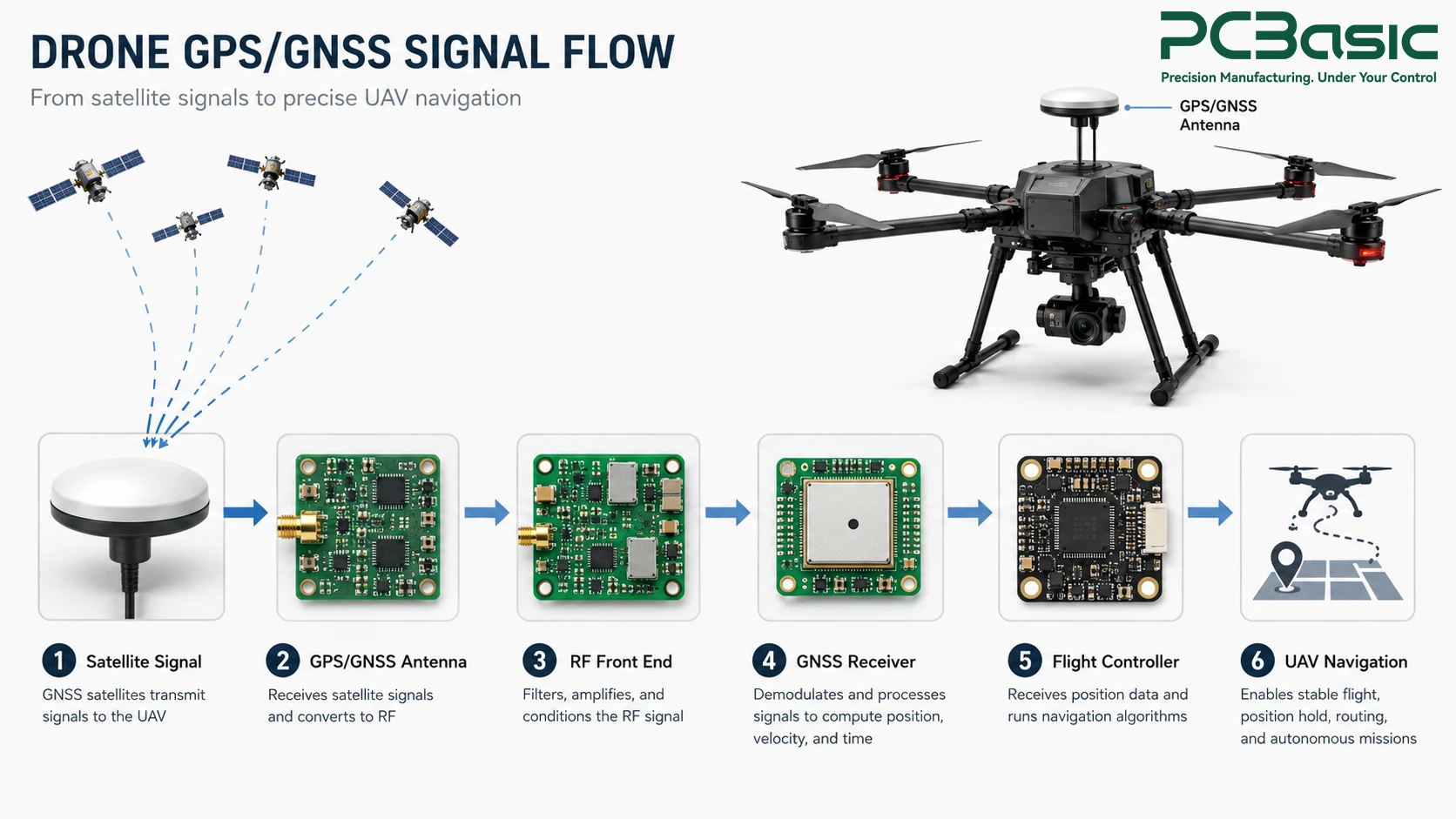
A common GPS PCB would consist of the RF front end, the GNSS receiver IC, a crystal oscillator that provides the time reference, a circuitry that ensures proper voltage regulation for power supply, and the interface, typically UART or SPI, for passing on data further. Also, many boards would incorporate an inertial measurement unit along with the GNSS receiver IC, because drones require position and short-range motion information to navigate.
Once the position information has been processed by the GPS module PCB, it is then fed to the flight controller, whereby the sensor fusion process combines the position information with barometer, compass, and IMU information. The result of this is that it forms the basis of the navigation process on board the UAV, enabling it to hold position, fly a path, or fly home. The GPS module is only one part of the broader drone PCBA, where navigation, sensing, communication, and power-control circuits must work together.
The behavior of the GNSS electronics is totally different from that of a normal digital control board since the signal to be received is much lower than the background noise. This makes the design process of the receiver quite crucial.
The distance of the trace, the impedance matching, and the ground plane continuity from the antenna to the chip of the receiver can all contribute to the quality of the signal. Poorly routed GPS PCB design may result in losing several decibels of the signal strength even before being processed by the receiver, resulting in poor satellite locking and reduced accuracy under weak signals such as dense urban or forest canopies.

The environment in which a drone operates electronically is a challenging one. The brushless motors controller, the high current battery wires, and even the video transmitter system all create electromagnetic noise that can easily end up directly in the GPS circuit board. Careful placement, a well-controlled ground and return-path structure, appropriate filtering or shielding, and sufficient separation from strong noise sources can help reduce interference coupled into the GNSS signal path.
Apart from RF performance, there are factors that influence the manufacturability of a board. Having very small clearance between components close to RF parts will look perfect on a computer, but it can cause many difficulties when producing the board, as the probability of solder bridging increases with the reduction of pitch. Engineers designing a GPS module PCB should weigh RF performance against realistic manufacturing tolerances early, rather than discovering the conflict after the first prototype run.
Panelization introduces additional considerations to this matter. A GPS module intended to go into mass production will be better served by having the PCB designed in such a way that panel breaking can be done efficiently without cutting too close to RF sensitive traces because of mechanical stress applied during the process.
A solid schematic only becomes a usable product once it survives the realities of component placement, soldering, and shielding on an actual production line.

The chipsets in GNSS receivers and RF front end modules are often designed as fine-pitch, compact modules, providing minimal allowance for placement errors. In order to create a reliable drone GPS module PCBA, high precision pick and place machines and highly accurate solder paste stencils are needed to ensure no bridging between adjacent pads.
GNSS modules, RF filters, oscillators, connectors, and other components may have different reflow and handling limits, so parameters such as ramp rate and peak temperature should remain within the requirements of the components used on the board. Poor soldering or thermal damage may create intermittent connections or degrade electrical or RF performance rather than causing an immediate hard failure.
External antenna connections require correct mechanical installation and reliable electrical contact. Threaded RF connectors may have specified torque requirements, while miniature snap-on connectors require proper alignment and full mating. Cleanliness requirements should follow the selected flux, assembly process, and product reliability requirements, particularly around sensitive RF areas. In order to verify operation, real verification requires turning on the board with a live antenna or GNSS signal simulator to obtain results for time to first fix, number of satellites tracked, and accuracy relative to an actual reference point.
Standard inspection catches a lot of defects, but it can't confirm the one thing that actually matters most for this category of board: whether it navigates accurately.

Solder paste inspection (SPI) tests for paste volume and location prior to the placement of any components. Automated optical inspection (AOI) checks the placement of components and solder joints after the reflow process, whereas x-ray inspection inspects below fine pitch packages and connectors, which cannot be seen visually. Together, these inspection methods can identify many physical assembly defects on a GPS module PCB, but they cannot by themselves verify GNSS reception or positioning performance.
In the next phase, the power supplies are verified as being in spec, the oscillator is verified as working at the correct frequency, and the UART or SPI interface is verified as communicating with a test fixture. This will identify wire problems and parts failures; however, a board may pass all electrical testing yet be a poor performer out-of-doors due to RF sensitivity issues.
To verify operation, functional testing may involve powering the board with a live antenna or GNSS signal simulator and evaluating parameters such as time to first fix, satellite acquisition, and positioning performance against a defined reference under controlled test conditions. This type of GNSS module testing actually allows for confirmation of performance of a drone GPS module PCBA as opposed to just passing a continuity check. PCBasic can support project-specific GNSS PCBA functional testing when the required test conditions, procedures, fixtures, and acceptance criteria are defined.
A single working prototype proves a design concept. Scaling that same performance across hundreds or thousands of units consistently is a different challenge entirely.
The chips of the GNSS receivers and RF front-end modules have encountered an issue of being in short supply, causing the temptation to use some replacement quickly to continue production. Any replacement must be tested for RF compatibility just like the original one before shipment in UAV GPS module PCBA because even the equivalent one can change the performance of the system in the field.
An approved list of vendors for components that require RF and pre-approved secondary sources help mitigate the risk of making an unqualified change due to time pressure. Such planning bears fruit most during the periods of shortage that take an unprepared team by surprise.

Consistent outputs require acceptance criteria that are specified quantitatively instead of just being subjectively approved as “looking good.” Acceptable minimum number of satellites, maximum time to first fix, and position error drift have to be quantified for pass/fail criteria prior to production, so that all GPS module PCB assembly meet the same criterion.
All firmware updates, redesigns of layouts, and different lots of components require a traceability back to a certain manufacturing date and test data. When a customer complains about a problem in navigation several months after implementation, it is only through traceability that a team of engineers can determine whether the problem lies in a firmware version, a certain lot of components, or an assembly modification, and this is something PCBasic does for all UAV navigation PCB programs it manufactures.
A drone’s capability to maintain a stable flight line eventually comes down to the design choices that were made much before even taking off: routing of the RF signal path, precision of the board assembly, and verification of its GNSS performance. The high-quality design of the drone GPS module PCBA sees all of them as related, not unrelated. If your team is working on the development or production of the navigation board for your drones based on GPS technology and needs an experienced manufacturer of RF sensitive PCBA, PCBasic's engineering team is ready to talk through your project.
Q1: What makes a drone GPS module PCBA different from a standard control board?
A1: This design focuses on an RF circuit that is capable of receiving very weak signals from satellites, which implies that the arrangement, shielding, and positioning of components are more critical here than for most other digital control boards.
Q2: Can standard PCB inspection confirm GPS accuracy?
A2: No. Automated optical inspection and X-ray inspections detect manufacturing flaws but it is only through functional GNSS testing using a receiver or signal generator that you can verify navigation capabilities.
Q3: Why does EMI matter so much for a GPS module PCB on a drone?
A3: Motor controllers, power leads, and video transmitters all have the potential to create sufficient electromagnetic interference to drown out the weak signal from the satellite if the GNSS portion of the circuitry is not shielded properly.
Q4: How does PCBasic verify UAV GPS module PCBA performance before shipment?
A4: PCBasic supports SPI, AOI, X-ray inspection, electrical testing, and project-specific functional testing according to the customer's design and test requirements. For UAV GPS module PCBA projects, GNSS functional verification can be implemented when the required test method, conditions, fixtures, and acceptance criteria are defined.

Assembly Enquiry
Instant Quote





Phone contact

+86-755-27218592
In addition, we've prepared a Help Center. We recommend checking it before reaching out, as your question and its answer may already be clearly explained there.
Wechat Support

In addition, we've prepared a Help Center. We recommend checking it before reaching out, as your question and its answer may already be clearly explained there.
WhatsApp Support

In addition, we've prepared a Help Center. We recommend checking it before reaching out, as your question and its answer may already be clearly explained there.
