
Global high-mix volume high-speed PCBA manufacturer
9:00 -18:00, Mon. - Fri. (GMT+8)
9:00 -12:00, Sat. (GMT+8)
(Except Chinese public holidays)





HomePage > Blog > Knowledge Base > PLC PCB Assembly: How Reliable Industrial Control Boards Are Built and Tested
Table of Contents
1. PLC Is Not a Common PCB: Components of the Controller
2. Why PLC PCB Assembly Is Different from the Common PCBA Process
3. From DFM Review to SMT/THT PLC PCB Assembly
4. How to Test PLC PCB Assembly Apart from Visual Inspection
5. From Prototype to Repeatable Production: Consistency of PLC PCBA
Hence, PLC PCB assembly means more than just putting the components on the PCB; it means dealing with such things as mixed signals, industrial noise, heat, connection reliability, component sourcing, and testing.
This article explains how PLC PCB assembly transforms a common PCB into a reliable industrial control board. It also explains how assembling a PLC control board differs from a general PCBA process.
A Programmable Logic Controller (PLC) is an industrial controller that executes programmed logic and interacts with other factory devices. Modern PLC designs can have a centralized or distributed architecture with interfaces for I/O, communications, and other field devices.
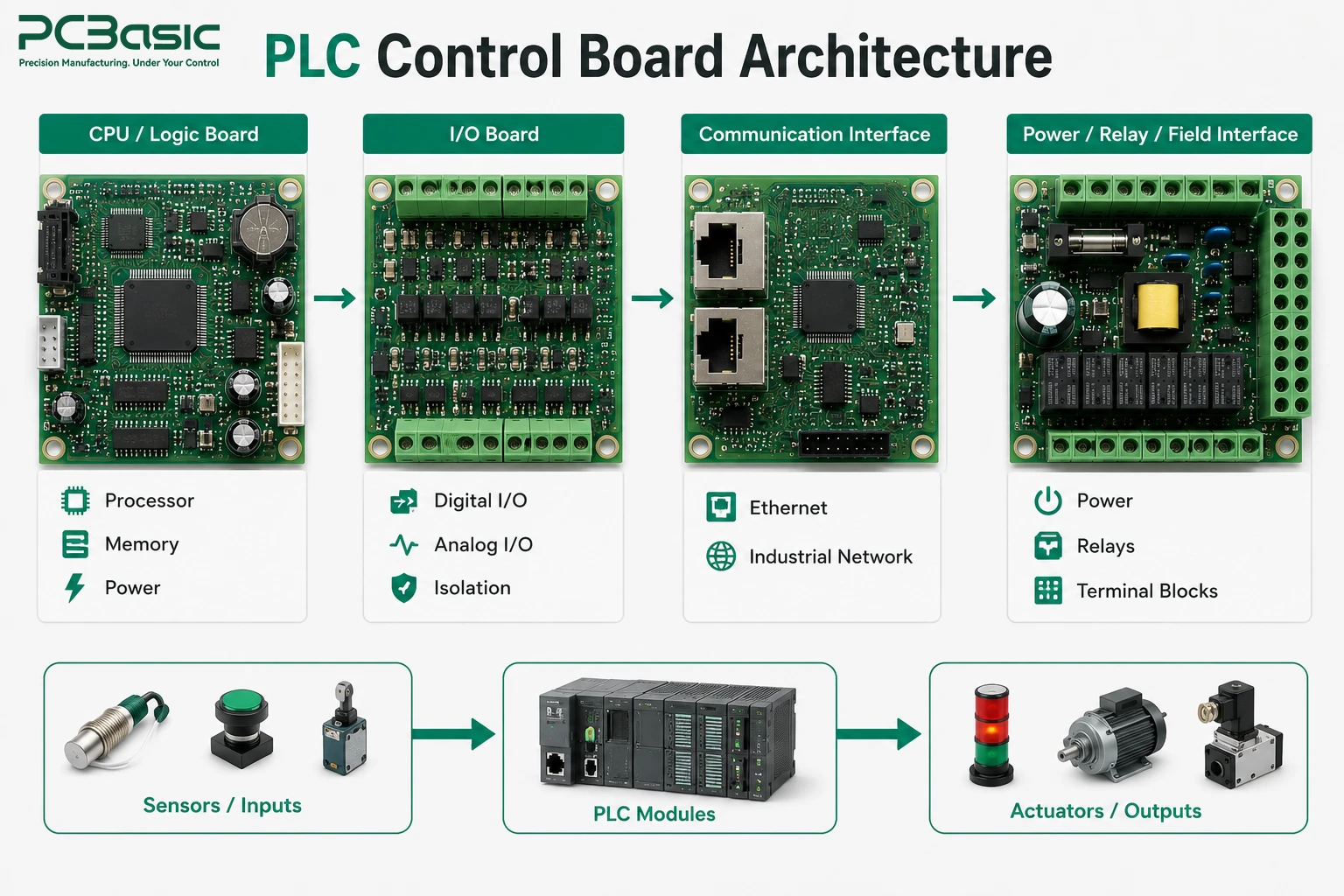
Many kinds of PLC control boards can be installed into a PLC system: some of them will handle CPU and logic functions, and some of them will handle I/O, communications, power supply, and field connections.
The CPU section is responsible for executing the control program and coordinating the operations of the PLC. It may include a microcontroller, microprocessor, memory units, clock circuits, voltage regulators, communication interface, and other protection elements.
Component selection is a major issue to consider when thinking about the speed and reliability of the operations performed. Engineers should take into account operating temperature, memory endurance and data retention, processor availability, EMC requirements, and power consumption.
A PLC controller PCB should have reliable power architecture. Voltage fluctuations and noise in processor rails may result in unpredictable behavior. Hence, design and PLC PCB manufacturing should pay attention to filtering, decoupling, grounding, power sequencing, and other similar issues.
I/O boards provide the interface between the controller and the environment. These circuits can manage digital inputs and outputs, analog signals, sensor inputs, or actuator commands. Communication boards handle network communication: modern PLCs may use Industrial Ethernet protocols such as PROFINET and EtherCAT.
Thus, a PLC PCB with high-speed communication interfaces may need special impedance control, careful positioning of the connectors, isolation, filtering, and protection from electrical transients.
Low-voltage electronics are needed in industrial control systems to control higher-energy field interfaces. Such components as relays, terminal blocks, optocouplers, isolation devices, fuses, transient protection, and power converters can be located on the same PCB.
One challenge in PLC control board assembly is that low-voltage electronics must operate reliably alongside field interfaces exposed to higher voltages, switching loads, and electrical transients.
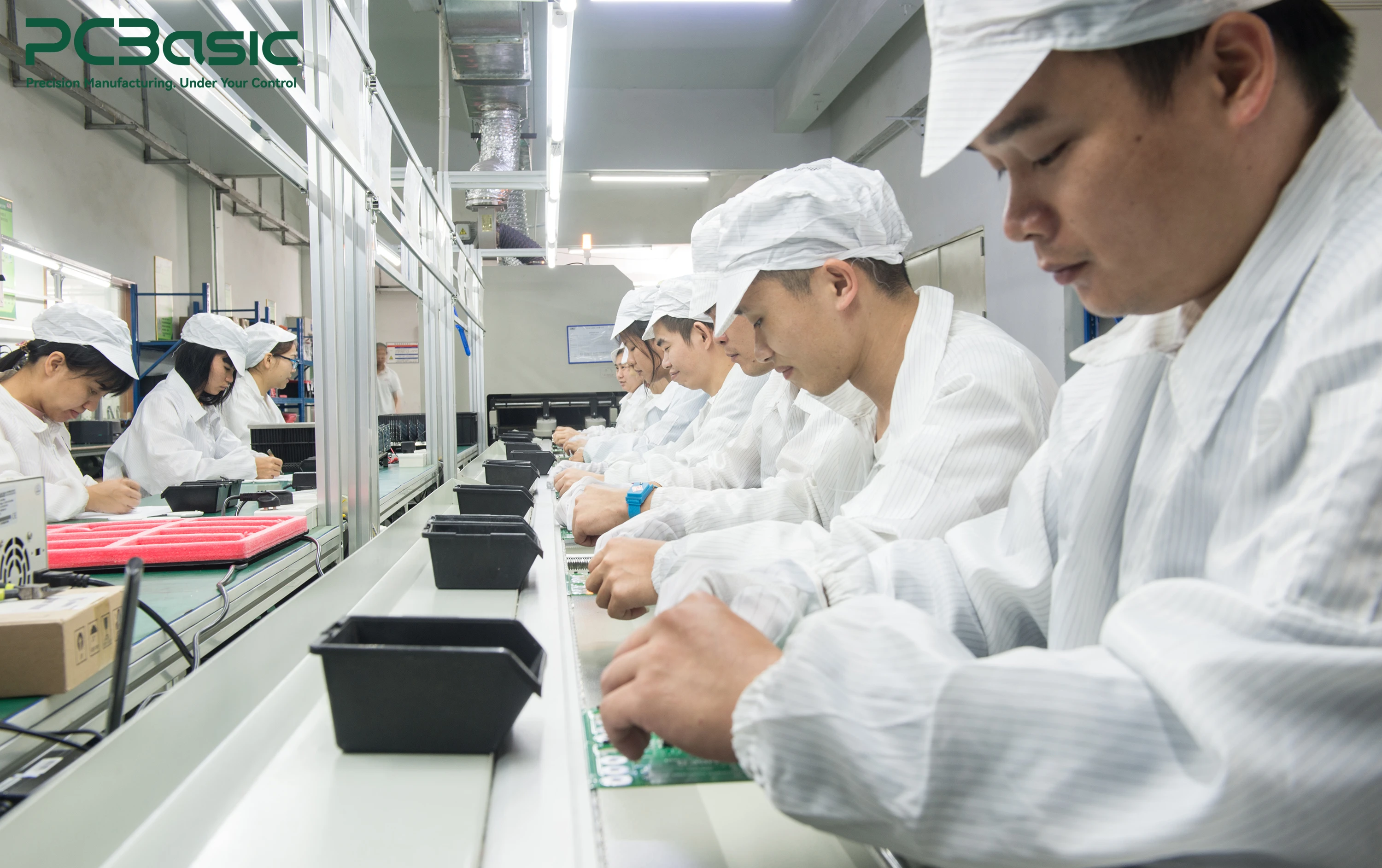
A key difference between PLC PCB assembly and common PCBA is the relationship between electrical performance and the environment. While many consumer PCBs work in controlled environments, a PLC board often has to work for years in environments where temperature, vibration, EMC interference, and electrical transients may occur.
Hence, the processes of industrial control PCB assembly and industrial automation PCB assembly need discipline in the design and manufacturing stages.
A PLC board can include processor circuits, switching outputs, analog inputs, communication interfaces, and power electronics. Each of these circuits brings in its own electrical problems: switching circuits produce noise; analog inputs need a stable reference voltage and well-controlled return path.
A common PLC PCBA can include fine-pitch ICs, small passive components, connectors, relays, transformers, terminal blocks, and through-hole components. Often, this implies the necessity to use both SMT PCB assembly and through-hole PCB assembly with different components, assembly processes, inspection, and thermal profiles.
IPC-A-610J gives the criteria for visual acceptability of electronic assemblies. J-STD-001J deals with soldered electrical and electronic assembly requirements and process controls.
Reliability starts before the first component reaches the assembly line. Designers have to consider creepage and clearance, thermal management, connector retention, mechanical stress, component derating, ESD protection, and EMC performance.
During high-reliability PCB assembly, the manufacturing process should remain coincide with the design requirements: any soldering defects, poor connection of connectors, or unapproved component substitution can lead to field failure of PLCs intended for long-time operation.

Successful PLC PCB manufacturing starts from engineering review, not from the assembly equipment. It helps to catch and fix issues early at the design stage, which can reduce costly changes later in production.
During DFM and DFA reviews, the PCB design is analyzed: board layout, component footprints, clearances, panelization, assembly orientation, solder mask openings, and test access.
Just as important is the Bill of Materials (BOM): long-lead components, obsolete parts, risk of counterfeiting, manufacturer-specific components, or package substitutions can interfere with production.
During the PLC control board assembly, engineers should identify which components directly influence critical functions or signal integrity. A substitute component may fit the same footprint, but it may still affect electrical performance.
Common SMT assembly starts with solder paste printing. Precise alignment of the stencil and controlled paste volume are very important, especially for fine-pitch processors and small passive components.
Then, the pick-and-place machine places components according to the assembly files. Exact placement is critical: excessive placement offset may lead to opens, shorts, or poor solder joints.
Reflow comes next, using the controlled thermal profile. It has to be tuned to the properties of the solder paste, board construction, component mix, and thermal mass.
PLC PCB assembly often needs a carefully chosen thermal profile for even heating and prevention of solder defects and component stresses.
Some large connectors, relays, transformers, terminal blocks, and other mechanically complex components can be assembled with the help of through-hole technology. Depending on the design, manufacturers may use such techniques as selective soldering, wave soldering, or manual assembly.
Flux residues and other contaminants may affect electrical performance or long-term reliability if they are not properly controlled during the assembly. Hence, the cleaning process should be chosen according to the soldering technique, component specifications, environment, and customer requirements.
Sometimes in industrial applications, conformal coating is used as protection for the circuit from humidity, dust, and other environmental effects. Coating should complement, not replace, PCB design and process control.
Visual inspection is just the first step in PLC PCB assembly testing. Successful testing requires multiple inspection and electrical verification techniques. The goal is to make sure that the PLC PCBA not only looks right, but also performs correctly—reads signals, processes them, and controls the outputs.
Solder Paste Inspection (SPI) checks the volume and placement of solder paste before the components are placed. It finds insufficient paste, excessive paste, or printing offset. AOI checks the presence, orientation, placement, and visible solder joints of the components. X-ray inspection provides visibility into hidden solder joints beneath packages where optical inspection is not possible.
IPC-A-610 defines the requirements for visual acceptability of electronic assemblies. According to IPC, X-ray inspection criteria are outside the scope of IPC-A-610, while related X-ray guidance is provided in J-STD-001. Together, these techniques provide broader inspection coverage for industrial automation PCB assemblies.
Inspection is not enough to check the electrical performance. In-Circuit Testing (ICT) verifies the electrical performance at accessible test points, detecting opens, shorts, wrong component values, and other assembly defects. Flying probe testing is a more flexible technique that is suitable for prototypes and low-volume production, since it does not require dedicated test fixtures. The choice depends on production volume, PCB complexity, test coverage, and design stage.
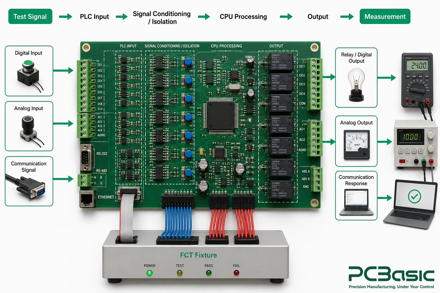
Functional testing is where PLC control board assembly goes beyond simple production verification. Test systems can send sample signals to the board and test its performance. For example, a digital input can receive an ON/OFF signal, and the analog channel can be tested with the specified voltage or current level. Thus, test equipment has to test the board's performance in signal processing.
Functional testing can simulate relevant signal paths and control functions of the board:
Signal input → signal conditioning → processing → output command → signal measurement.
It provides functional verification that visual inspection alone cannot provide.
Choosing the right PLC PCB assembly partner is more than just a comparison of assembly service prices. Industrial customers need to be sure that their PLC PCBA stays consistent throughout its lifecycle: prototyping, piloting, and repeated production.
During prototyping, the goal is to quickly detect and resolve design issues while verifying circuit performance. During pilot production, the focus changes to process stability. DFM findings, test procedures, assembly instructions, and component sourcing should be carefully controlled. At the stage of mass production, the goals are repeatability, yield, throughput, traceability, and cost.
Industrial products often have relatively long product lifecycles. Therefore, a processor or any other component that is available at design time may become obsolete during the product lifecycle. Consequently, a PLC PCB assembly company should manage controlled component data and approved alternative components.
Traceability becomes critical when the same industrial control PCB assembly design is used in multiple production batches. It can include PCB revision, BOM revision, component lot numbers, assembly date, machine and process data, inspection results, test results, and operator or equipment identification. Change control helps maintain this consistency: component substitutions, stencil changes, firmware updates, or process changes have to be performed according to an approved procedure and documented.
The whole process of PLC PCB assembly has to combine engineering, sourcing, production, inspection, and testing. A capable PLC PCB assembly supplier may provide:
1) DFM/DFA review prior to production
2) SMT/through-hole production
3) Industrial component sourcing
4) SPI/AOI inspection
5) X-ray inspection (if necessary)
6) ICT/flying probe testing
7) PLC PCBA functional testing
8) Conformal coating (if necessary)
9) Production traceability
10) BOM and revision control

Assembly of a PLC PCB involves not only attaching the components to the circuit board. As PLC PCBs are often used in tough industrial conditions, they may need to withstand electrical noise, temperature variations, vibration, and constant operation.
Hence, reliability should be considered throughout the whole manufacturing process—from a detailed analysis of the PLC PCB design and its components before manufacturing to proper SMT and THT assembly, inspection, and electrical and functional testing.
For manufacturers of PLC controllers or other industrial automation equipment, proper manufacturing support is very important. PCBasic supports projects from prototype builds to mass production, including engineering review, component sourcing, PCB manufacturing, assembly, testing, and production management.
Finally, the reliability of PLC PCBs depends on proper planning, manufacturing, and testing.
Q1: What is PLC PCB assembly?
A1: PLC PCB assembly is the process of assembling electronic components onto printed circuit boards used inside programmable logic controllers.
Q2: What components can be found on a PLC control board?
A2: A PLC control board can have processors, memory devices, voltage regulators, communication chips, connectors, relays, isolation components, protection components, analog circuits, and digital I/O circuits.
Q3: Why PLC PCB assembly uses both SMT and THT?
A3: A PLC board can have small and high-density components along with mechanically complex components like terminal blocks, connectors, relays, and transformers.

Assembly Enquiry
Instant Quote
Phone contact

+86-755-27218592
In addition, we've prepared a Help Center. We recommend checking it before reaching out, as your question and its answer may already be clearly explained there.
Wechat Support

In addition, we've prepared a Help Center. We recommend checking it before reaching out, as your question and its answer may already be clearly explained there.
WhatsApp Support

In addition, we've prepared a Help Center. We recommend checking it before reaching out, as your question and its answer may already be clearly explained there.
