
Global high-mix volume high-speed PCBA manufacturer
9:00 -18:00, Mon. - Fri. (GMT+8)
9:00 -12:00, Sat. (GMT+8)
(Except Chinese public holidays)





HomePage > Blog > Knowledge Base > Automotive PCB Assembly: Reliable, Traceable Processes
Table of Contents
1. Why Can an Automotive PCB Work Once but Fail in Repeat Production?
2. Which Build Details Should Be Locked Before Assembly Starts?
3. How Should Soldering and Inspection Controls Match the Board?
4. What Does a Useful Functional Test and Traceability Record Include?
5. What Should an Automotive PCB Assembly Quote Cover?
What happens when the first batch of automotive PCB assemblies powers up normally and passes testing, but the next batch behaves differently?
The problem is often not a single obvious defect. Component lots may change, approved substitutes may not be clearly documented, connector orientation requirements may be overlooked, or functional tests may be conducted under different load conditions. Taken individually, each change may seem small, but each one can affect production consistency.
Reliable automotive PCB assembly, therefore, is not just about making one board work properly. Approved files, materials, process controls, inspection methods, test conditions, and traceability records need to remain consistent from one production batch to the next. This article explains which manufacturing controls help turn a working prototype into a repeatable production build.
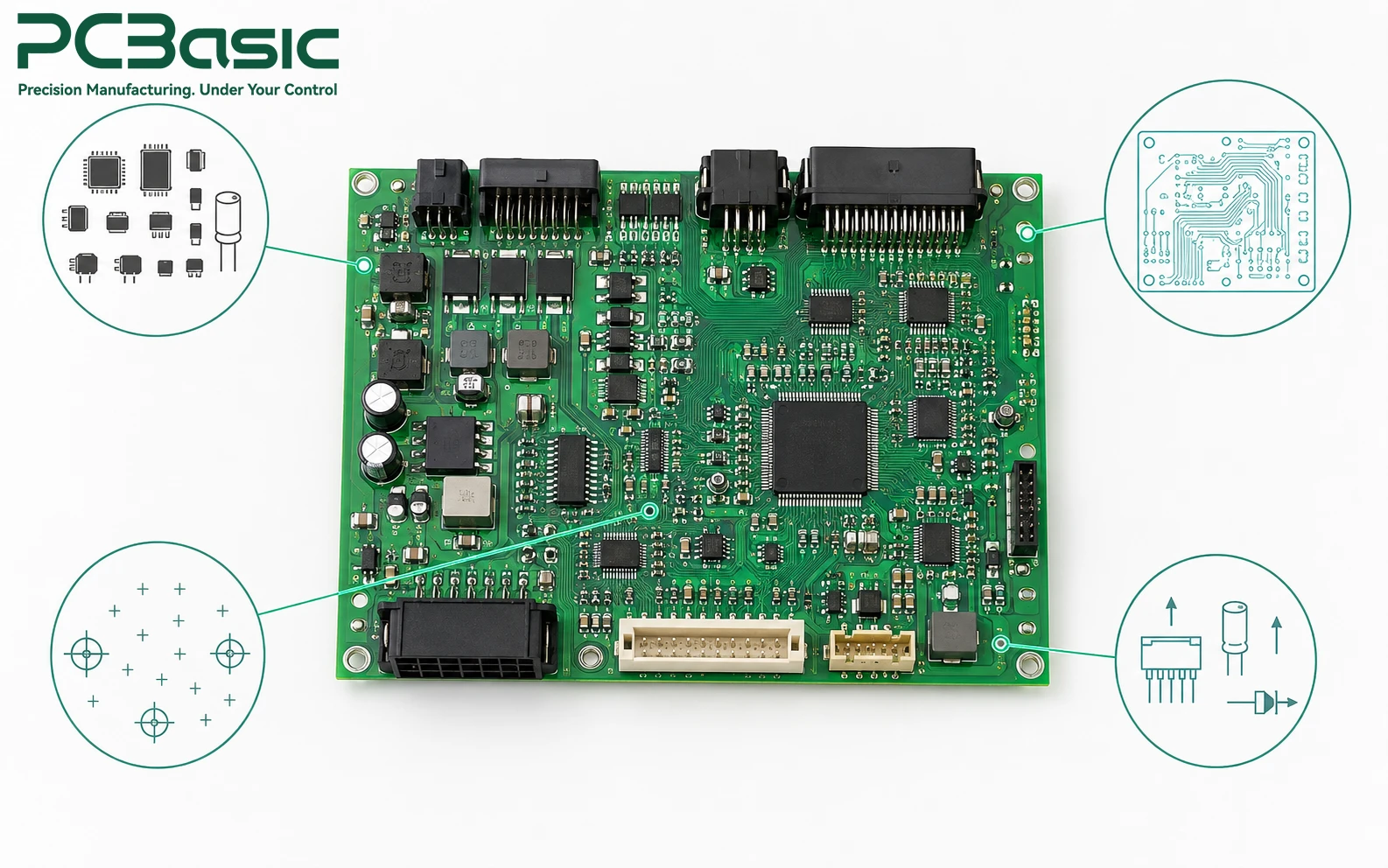
Automotive electronics often fail at the handoff between an engineering intention and a manufacturing instruction. The schematic explains the circuit, but it does not automatically specify which component alternates are acceptable, which connector must be checked for retention, which bottom-terminated packages need X-ray inspection, or how a functional test should reproduce the operating condition. Those decisions need to be explicit before the build begins.
A practical review starts with the board function. A power board needs more than a component placement check: the team should identify the current path, the high-current paths, power terminals, thermal interfaces, and the load used for verification. A communication or sensor board needs a defined connector mate, firmware revision, and expected input/output behavior. The production route then follows the risk, rather than treating every component as if it needed the same inspection.
Build Control Map for Automotive Electronics
|
Board area |
Key risk |
What to control |
|
Power stage / high-current connector |
Overheating, weak retention, or poor performance under load |
Orientation, retention, solder coverage, load conditions |
|
BGA / QFN / bottom-terminated components |
Hidden solder-joint defects |
X-ray scope and acceptance criteria |
|
Sensor / communication interface |
Wrong substitute, polarity, or connector orientation |
Approved BOM, polarity, firmware, functional test |
|
Revision & batch record |
Difficult fault tracing |
Revision, material ID, inspection, rework, test records |
Buyer inputs should match the identified risk. For example, power assemblies may require current, voltage, connector, retention, and load-test requirements, while hidden-joint packages need defined X-ray scope and acceptance criteria. Sensor or control interfaces may require an approved BOM, firmware revision, mating conditions, and expected signals. Traceability requirements should also define the revision release point, required record fields, retest rules, and delivery records.
These inputs do not replace the product team's engineering responsibility. Instead, they give the supplier enough information to translate design intent into defined manufacturing and acceptance criteria. This helps prevent acceptance conditions from being inferred from Gerber files, photographs, or a partial BOM. When the requirements and buyer inputs are documented together, the build can be reviewed against a shared set of controls rather than a general promise of high quality.
Start by separating files according to the job each one performs. Gerber and drill data define fabricated-board features. The BOM identifies approved parts and alternates. Pick-and-place data tells the line where and in what orientation to place components. Assembly drawings carry polarity, connector orientation, keep-out, special handling, and manual-insertion notes. A test instruction sets the power source, connected load, interfaces, expected outputs, limits, and record format. None of these files can safely substitute for the others.
For an automotive PCBA manufacturing project, the BOM is especially important when a component is difficult to source or has an approved alternate. The substitute should be checked for its electrical function, package compatibility, thermal behavior, and whether the planned functional test is capable of detecting any relevant difference. PCBasic's component sourcing support can help connect BOM review with procurement and assembly, while the product team retains approval of any change that can affect the intended function.
The same discipline applies to mechanical details. Call out the mounting hardware, connector engagement, heat-spreader contact, coating boundary, label position, and any fixture restriction that changes how the board is handled. A drawing note that identifies a specific connector face or a no-coating zone is more useful than a general instruction to assemble carefully.
Inspection becomes useful when each method answers a specific question. SPI checks the printed solder paste before reflow; it does not prove that a connector carries the required load. AOI can identify visible placement, polarity, marking, and solder-joint conditions; it cannot confirm a hidden joint or the board's electrical behavior. X-ray is appropriate where a solder connection is concealed, such as a BGA, QFN, or other bottom-terminated device. Functional testing checks the defined behavior under the stated conditions, not every possible vehicle-level condition.
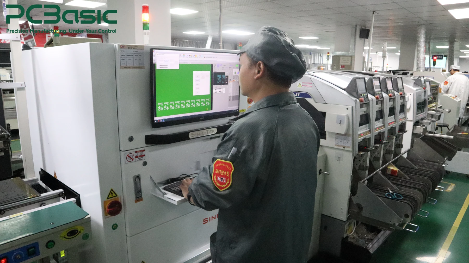
This distinction matters for high-reliability automotive PCB assembly. A board that combines dense SMT devices with through-hole power terminals may require separate controls for solder paste release, reflow, wave or selective soldering, manual touch-up, and mechanical retention. PCBasic's documented production route includes SPI, AOI, X-ray, first-article inspection, pre- and post-wave-soldering DIP AOI, and functional testing. The buyer should name which of those controls applies to each risk, along with the acceptance condition and the record to retain.
When the board files are ready, PCB assembly services should be evaluated against the actual mix of SMT, DIP, hidden joints, and test access rather than against an undifferentiated equipment list.
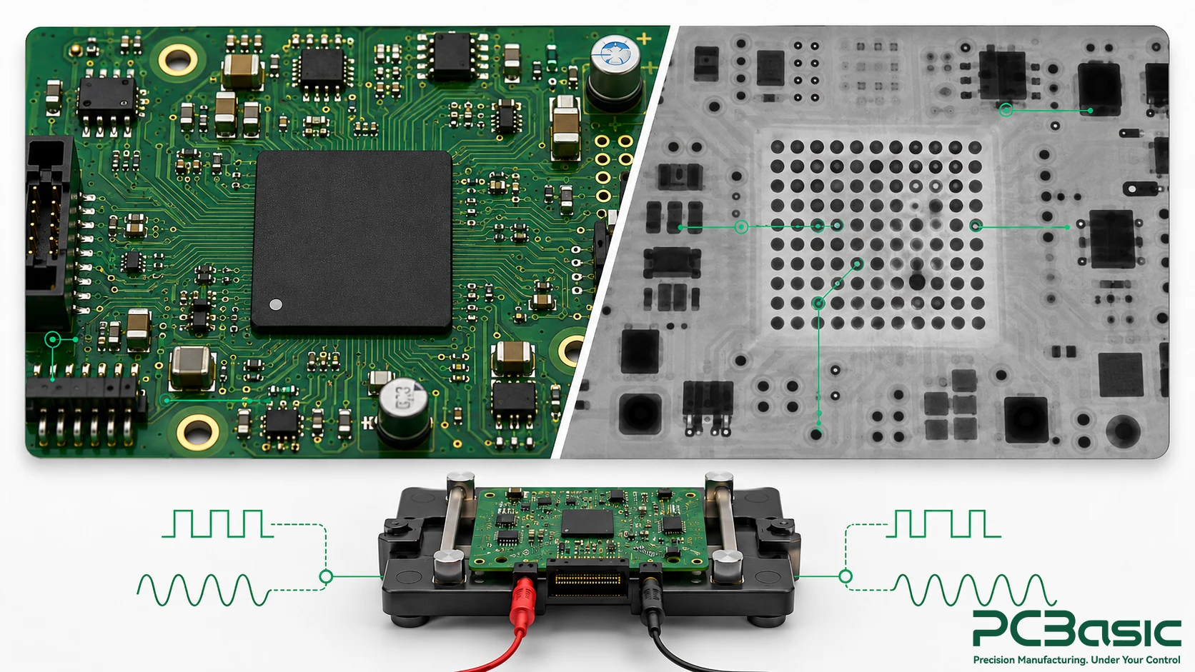
A useful test plan recreates enough of the board's intended use to expose electrical or functional faults that visual inspection cannot detect. It should state the PCB revision, firmware or programmed configuration where applicable, supply voltage, connected load or simulator, interface condition, expected signals, permitted limits, and the reason a unit is accepted or rejected. A pass/fail label without the conditions behind it makes later comparison difficult.
Traceability should connect the evidence to a particular build, not simply store documents in separate folders. Keep the released BOM and board revision, incoming-material result, first-article decision, relevant process checks, rework or retest history, functional outcome, and shipment identifier in a retrievable chain. PCBasic uses IQC incoming inspection, first-article systems, and MES-based production records. That capability is most valuable when the project has already defined the fields that need to stay together.
For a traceable automotive PCB assembly build, use the PCBA functional testing service to align fixture needs and test steps with the actual board behavior, then decide which results must accompany each batch.
Do not turn a manufacturing record into a claim that the finished vehicle system is compliant or fault-free. Vehicle-level validation, software requirements, environmental qualification, and regulatory acceptance remain responsibilities defined by the automotive program and the relevant OEM, Tier supplier, or product owner. The manufacturing record makes the board-level build easier to compare, investigate, and repeat.
A quote that names only quantity, lead time, and a BOM leaves too much open. State the project stage, board and BOM revisions, approved alternates, panel or special-process needs, programming responsibility, test coverage, fixture status, enclosure or cable work, coating requirement, labeling, packaging, and required batch records. If a connector, power terminal, BGA, or sensor interface has a known risk, make the required check visible in the quotation package.
This is where the quality control system becomes relevant: it should carry a defined engineering requirement through incoming inspection, assembly, inspection, test, and final QA rather than appear as a separate marketing claim. For teams comparing automotive PCB assembly services, the better quote is the one that makes these decision points visible before production begins.
The final review should also identify what remains outside the assembly scope. Clarify who approves a substitute component, owns firmware release, supplies test fixtures, defines the vehicle-side mating condition, and accepts the finished unit. Clear ownership prevents a manufacturing question from becoming a late-stage field problem.

Reliable automotive PCB assembly is a controlled build, not simply a populated board. The project becomes easier to repeat when every important board function has a matching manufacturing control, inspection method, test condition, and retained record. That gives the production team enough direction to build consistently and gives the product team evidence to compare one batch with the next.
When the board files, BOM, and test conditions are ready, share your build package with PCBasic so the assembly path, component controls, and required records can be reviewed together before supplier evaluation is reduced to price and lead time alone.
Q1: Does IATF 16949 certification make a PCB assembly automatically suitable for every automotive program?
A1: No. A quality-management certification does not replace project-specific requirements. The buyer still needs to define the approved files, materials, inspection scope, test conditions, traceability fields, and acceptance criteria for the board.
Q2: Which automotive PCBA manufacturing records are most useful when a field issue is investigated?
A2: Start with the released board and BOM revisions, approved alternates, material identification, first-article decision, relevant inspection results, rework or retest record, functional test result, and shipment or batch identifier. The exact list should match the project's defined risks.
Q3: Can AOI replace X-ray or functional testing?
A3: No. AOI checks visible placement and solder conditions. X-ray is used for hidden solder joints where required, while functional testing checks the specified electrical behavior. A sound inspection plan assigns each method to the condition it can actually verify.
Assembly Enquiry
Instant Quote

Phone contact

+86-755-27218592
In addition, we've prepared a Help Center. We recommend checking it before reaching out, as your question and its answer may already be clearly explained there.
Wechat Support

In addition, we've prepared a Help Center. We recommend checking it before reaching out, as your question and its answer may already be clearly explained there.
WhatsApp Support

In addition, we've prepared a Help Center. We recommend checking it before reaching out, as your question and its answer may already be clearly explained there.
