
Global high-mix volume high-speed PCBA manufacturer
9:00 -18:00, Mon. - Fri. (GMT+8)
9:00 -12:00, Sat. (GMT+8)
(Except Chinese public holidays)





HomePage > Blog > Knowledge Base > Smart Home PCB Assembly: How Wireless Design, Power Control, and Testing Shape Reliability
Table of Contents
1. What Does a Reliable Smart Home PCBA Actually Need to Do?
2. Wireless Design Decisions That Continue to Matter During PCB Assembly
3. Power Control, Safety, and Thermal Design Vary by Smart Home Product
4. From Design Files to Production-Ready Smart Home PCB Assembly
5. Testing and Manufacturer Evaluation Should Follow Real Product Risks
The smart home market is going to generate close to $164 billion in terms of market value in 2026 and should keep growing in the double-digit numbers through at least the beginning of the 2030s, according to research conducted by industry experts at Mordor Intelligence. The growing number of product types, shortened timelines, and decreasing margin for error in terms of connectivity or safety features make it increasingly important to know what smart home PCB assembly entails.
This article will discuss all aspects of PCB assembly for smart homes, which involves a number of decisions regarding wireless and power transfer that become essential at the design stage and how the process is carried out when the design documents are available for making an operational circuit board.
While each component in smart home systems might look different, like the video doorbell and the smart irrigation valve, the function of the printed circuit boards remains alike in both cases. Good home automation printed circuit board assembly works by detecting the environment, processing data, connecting to the network, and carrying out instructions using battery energy in a small area.
In most cases, the structure of a smart home board consists of four main functional blocks within one PCB – input/sensor circuitry, microcontroller, wireless radio and output circuitry that controls relays, LEDs, or motors. It means that the distinction between IoT PCB assembly for smart home devices and common single-function board assembly becomes clear.
Putting all four functional blocks onto one board and still making sure that they do not interfere with each other is the most difficult aspect of the smart home controller PCB assembly process. For instance, when the processor clock trace is routed too close to sensitive RF circuitry, it may introduce interference and reduce wireless performance before the problem is noticed.
For a battery-operated leakage detector, it is crucial for the current draw when in a quiescent state to be low. An electrical isolation feature along with good thermal management is essential for a smart plug connected to an AC source. A proper design of interface circuitry for the camera is important for signal integrity. There are no correct layouts of smart home products; there are only good ones.
Wireless capabilities are determined theoretically, but ultimately proven or disproven in the manufacturing process. Wi-Fi smart home PCB assembly, together with its other counterparts such as Bluetooth, Zigbee, and Thread, depends on choices which cannot be determined by any schematic.
A locking mechanism that has to run for a whole year using battery power is definitely not ideal for Wi-Fi because it uses much more energy compared to Zigbee and Thread protocols. Yet, there should be enough power processing abilities in the central node in order to manage several radio transmitters at the same time. Thus, choosing the protocol and the wireless module PCB assembly technology according to this protocol will prevent any changes in the design process in the future.
This means that an antenna that functions well without any other component in the circuit may not work as well when enclosed in plastic, placed near a metallic enclosure, or packed tightly against a battery pack.
Ensuring the clear space around the antenna, proper selection of the antenna according to the enclosure material used, and testing the performance of the antenna in conjunction with the enclosure and not just the circuit board is very important. The success of a smart plug in reconnection instantly versus its success for some weeks before needing a router restart could depend on it.
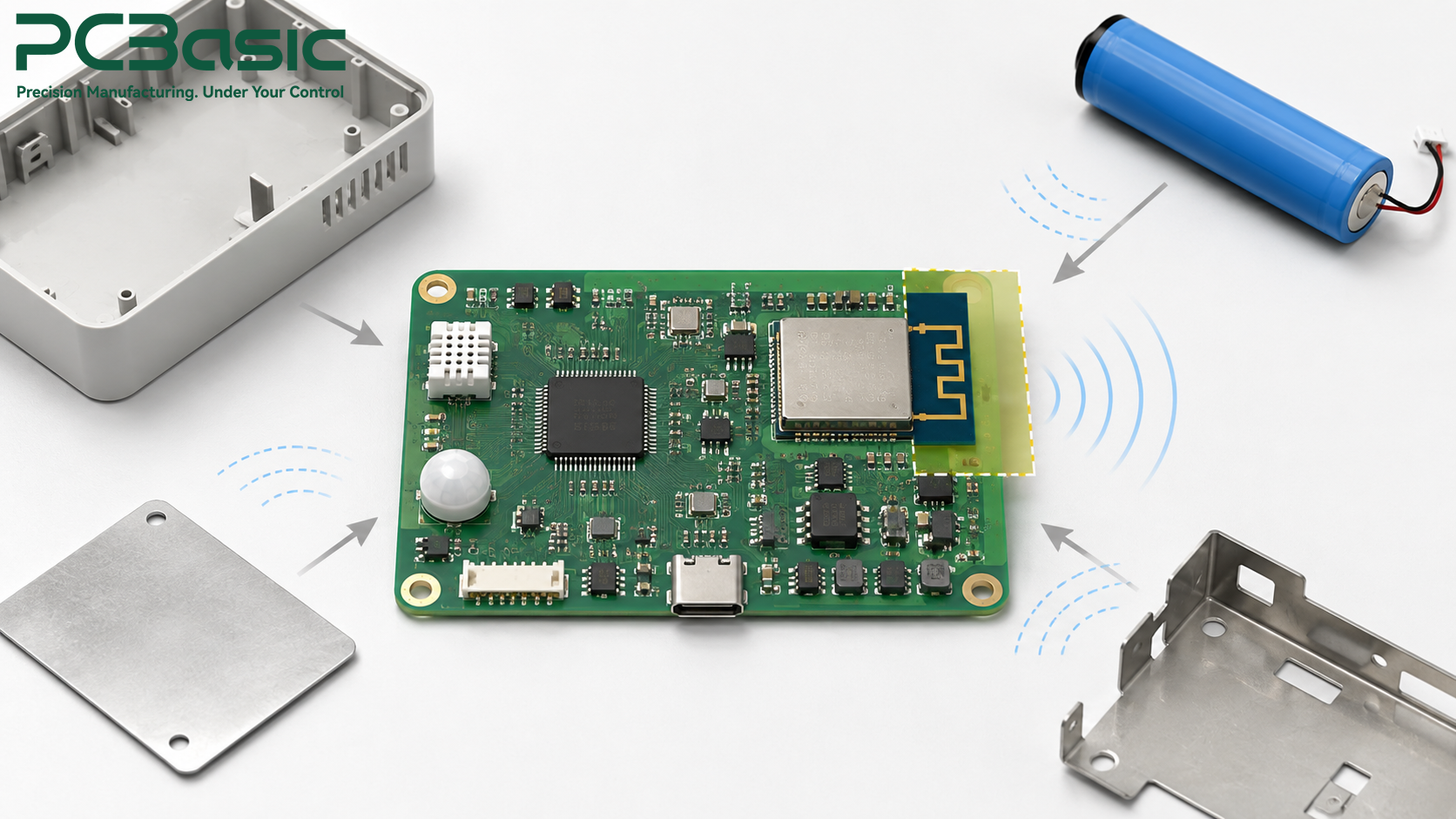
The tolerances of the components, the amount of the solder paste, even the temperature within the reflow oven may result in small fluctuations in the tune of the antenna matching circuit. While one particular sample proves to be outstanding, boards produced later in volume production may show small variations in performance. The integration of Wi-Fi modules and proper process management during wireless smart home PCBA manufacturing help prevent the issue from reaching customers.
Power requirements for electronics that operate inside a smart house are never universal. Power requirements for a sensor that operates on microamps are entirely different from those of a switch operating at mains voltage.
Sensors and battery-operated modules will remain asleep throughout their entire life except when they occasionally wake up to provide information about themselves. In order to maintain balance between the two, one needs to make proper selection of regulators with low quiescent current and sleep mode of the microcontroller without affecting its performance.
The aggressive approach to energy consumption leads to a slow response time, while insufficiently aggressive results in quick discharge of the battery power.
The PCB assembly process of smart plugs and smart lighting controllers entails integrating low-voltage circuits with high-voltage circuits on a single PCB. This kind of PCB assembly raises some extra difficulties in terms of creepage/clearances, isolation boundaries, and components' ratings since any mistake in the design may become dangerous rather than annoying.
Depending on the product and target market, manufacturers may need to meet applicable product-specific safety standards such as IEC 62368-1 or UL 62368-1 and verify the required creepage and clearance distances.
Relays that switch high currents also produce heat and electrical noise that may enter adjacent circuits if not isolated by proper circuit layout. Thermal vias, proper copper fill, and spacing between the power section and analog/RF circuits will ensure that a temperature sensor reads the temperature accurately without a slight increase, while a wireless module does not pick up electrical noise from the switching process.
Converting the design process to manufacture the product is not simply sending Gerber files to the manufacturing facility. The process of ensuring that the smart home PCB assembly works successfully includes four steps.
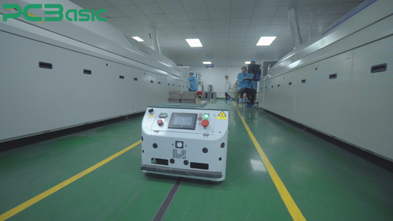
DFM review analyzes the trace width, hole size, and spacing at the design phase before moving into production. The manufacturer will also review the Bill of Materials at this stage to ensure that components will be available and that their lifespan is not compromised through obsolescence during the manufacture process.
It is also at this stage that the manufacturer reviews the product functions since some parts like the outdoor IP sensor and the indoor hub may require different treatment in terms of conformal coating and enclosure sealing despite being similar on the circuit board.
Bare board manufacturing and component procurement are done simultaneously if need be in order to ensure some level of lead time. As for home automation PCB assembly, the process entails the procurement of RF modules, sensors, and connectors from reputable sources since counterfeit RF modules are responsible for unreliable wireless communications.
SMT assembly process is carried out through mounting and soldering of the components through the use of the automatic placement equipment and reflow oven. The process is followed by automatic optical inspection to check any problems arising from wrong placements, solder bridges and missing parts. In the case of circuit boards having wireless modules, the process entails the correct placement of the modules along with the manual soldering of connectors or shielding cans not within the capacity of the automatic equipment.
Going from a few prototypes to a large production straightaway skip over the stage where all the hidden flaws will show up. If a few hundred pieces of the pilot program are run, it will reveal any process variations, weak links, or connection issues that cannot be found out through ten pieces of prototypes.
Testing is where design ideas meet physical reality. It helps determine whether a product will perform consistently or lead to warranty claims.
Automated optical inspection (AOI) can identify visible defects such as component misalignment, solder bridges, and tombstoning, while X-ray inspection may be used for BGA, QFN, LGA, or other packages with hidden solder joints. It would be much more cost-effective to detect such defects than to discover them later.
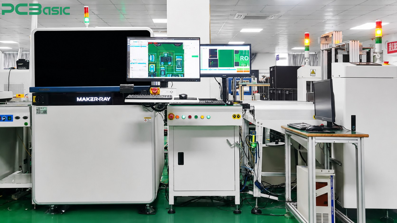
In-circuit testing verifies the connections and component values against the specification, whereas flying probe testing provides an alternative approach for smaller batches of production. The firmware is loaded onto the board and tested for its basic functioning.
Smart home PCBA functional testing must incorporate how the product will actually be used, rather than just verifying proper flow of current in the circuit. These may include verification of association to Wi-Fi and proper Wi-Fi coverage through a shielded room, verification that the relay is able to switch a correct load without overheating, and that the sensor is giving correct readings in its full scale. Smart home PCB assembly testing based on real-life operating conditions can detect flaws that may not be revealed by a simple continuity test.
Here are the things you should be paying attention to while evaluating a smart home PCB assembly manufacturer:
Do they have any previous experience with RF design and wireless certification testing? Which safety standards do they check their PCB assemblies with mains connections for?
Can they provide any information about the inspection and testing of a similar smart plug PCB assembly or smart lighting control PCB assembly? If they can give a definite answer and show process documentation for it, pay attention to such a manufacturer.
That’s why PCBasic implements the above rule into every smart home PCB assembly project from the design for manufacturing review through functional testing. Connected home solutions have to prove themselves right from the very beginning as a connection failure or overheating of the plug will harm the client's trust instantly, no matter how good the firmware update will be later on.

Smart home electronic products are about more than design—quality assembly is crucial too. Wireless reach guaranteed in a brochure, margin of safety needed for a plug that plugs into the mains supply, and performance reliability across many, many units rely on quality smart home PCB assembly.
No matter if the product is a battery-operated sensor, a Wi-Fi-connected smart home PCB assembly, or a mains-rated lighting controller, the manufacturing partner is every bit as critical as the design itself. PCBasic is your manufacturing partner, helping you bring your smart home product to market and beyond.
Q1: What makes smart home PCB assembly different from standard PCB assembly?
A1: A smart home control board generally combines a radio unit, sensor, and, sometimes, even mains switching on one board. This is why RF design aspects and heat sink issues take prime importance in contrast to ordinary consumer electronic designs.
Q2: How long does a typical smart home PCBA project take from design to production?
A2: The time period depends on the level of complexity of the project, but the DFM analysis, prototyping, and trials generally take a couple of weeks before starting mass production. The process of wireless certification can also add to the overall timeline.
Q3: Why does antenna placement matter so much in smart home devices?
A3: The enclosure, battery pack, and metallic components can affect antenna performance compared with an antenna operating without the enclosure. This is why the wireless range of the module should be tested with the enclosure, and not just on the PCB level alone.
Q4: What testing should a smart plug or lighting controller go through before shipping?
A4: Apart from electrical testing, there is a need for these devices to be put through functional testing, thermal testing, and safety isolation testing at their rated load. This is vital since these devices incorporate control electronics with mains switched devices.
Q5: How do I choose the right smart home PCB assembly manufacturer?
A5: Select a firm that has been known in the industry for its success in RF testing and safety testing, together with inspection certificates and transparency on how they tested the same kind of item as your product. This way of thinking is way superior to simply going by manufacturing capabilities.

Assembly Enquiry
Instant Quote


Phone contact

+86-755-27218592
In addition, we've prepared a Help Center. We recommend checking it before reaching out, as your question and its answer may already be clearly explained there.
Wechat Support

In addition, we've prepared a Help Center. We recommend checking it before reaching out, as your question and its answer may already be clearly explained there.
WhatsApp Support

In addition, we've prepared a Help Center. We recommend checking it before reaching out, as your question and its answer may already be clearly explained there.
