Global high-mix volume high-speed PCBA manufacturer
9:00 -18:00, Mon. - Fri. (GMT+8)
9:00 -12:00, Sat. (GMT+8)
(Except Chinese public holidays)
Global high-mix volume high-speed PCBA manufacturer
9:00 -18:00, Mon. - Fri. (GMT+8)
9:00 -12:00, Sat. (GMT+8)
(Except Chinese public holidays)
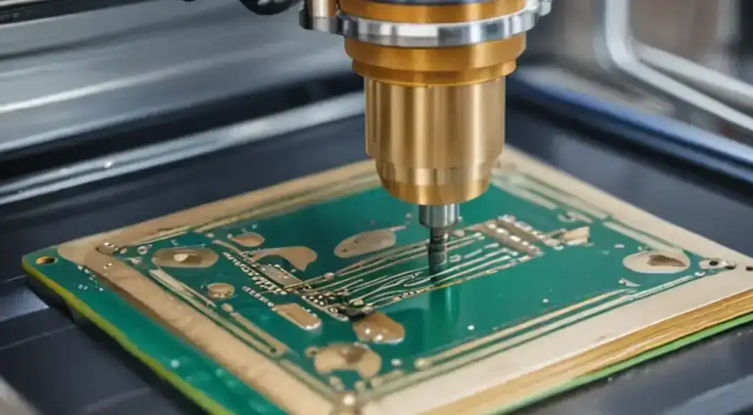
As electronic products become smaller and more powerful, the manufacturing precision of circuit boards also needs to be continuously improved. PCB Z-Axis Milling is a machining method that uses a CNC machine to cut circuit board materials along the vertical direction. It can mill grooves, openings or cavities on the circuit board for placing components, reducing the weight of the board or improving electrical performance.
This process is often used in the processing of HDI boards, RF boards, and multi-layer complex circuit boards. It has very strict requirements for depth control, and even a slight deviation may damage the internal copper layers or circuit traces.
When designing the Z-axis milling of a PCB, some basic mechanical and dimensional rules need to be followed to ensure accurate processing and easy board production.
|
Design Parameter |
Value |
|
Minimum mill tool diameter |
0.8 mm |
|
Standard mill tool diameter |
2.0 mm |
|
Special mill tool diameter |
0.8 mm ≤ Ø ≤ 2.0 mm |
The outer shape and internal openings of a PCB can be processed according to design requirements. The outer corners can be either right-angled or rounded, while inner corners must have a radius no less than the radius of the milling tool. Only in this way can it be convenient for processing, and the corner will not be chipped or the tool will not break.
1. Edge milling is generally included in the standard PCB manufacturing and does not charge separately.
2. It is not recommended to mill into the copper layer to avoid affecting the strength of the board or causing delamination.
3. In the design documents, it is recommended to mark board outlines of the board with a 0.2mm line width. The
The path of the milling cutter usually runs in the center of these lines to ensure the accuracy of the dimensions.
Overall, as long as the size, depth and spacing of the milling cutters are reasonably set, Z-axis milling can achieve high processing accuracy, good stability and consistent quality.

Z-axis milling can precisely control the milling depth and process stepped cavities, embedded components and other structures, which is something that ordinary etching processes cannot achieve.
Milling is a pure mechanical process that does not use chemical solutions, making it more environmentally friendly and highly suitable for prototype and small-batch production.
A single CNC machine can complete various operations such as drilling, slotting and Z-axis milling, saving time and improving production efficiency.
Milling is not as prone to over-processing as etching. It can maintain the stability between layers of the sheet, make the cut cleaner and the bonding stronger. It is especially suitable for the production of thick plates and multi-layer plates.
PCB Z-axis milling is widely used in various industries and PCB designs, including:
1. Cavity Milling – Used to machine grooves or cavities for embedded chips or passive components.
2. Slot and Cut-Out Milling – Creates slots or openings for connectors, heat sinks, or mechanical fittings.
3. Step Pocket Milling – Mills specific areas to achieve different board thicknesses.
4. V-Scoring and Panel Separation – Cuts along predefined lines to separate PCB panels efficiently.
5. Thermal Cavity Milling – Forms recesses in high-power circuits to improve heat dissipation.
6. Controlled Impedance Design – Adjusts dielectric thickness precisely to ensure signal integrity in RF and high-speed boards.
PCB Z-axis milling is a very crucial step in advanced circuit board manufacturing. It is more flexible and precise than traditional etching or edge milling methods, and can also precisely control the milling depth. Whether it is for embedded components, enhancing RF performance, or reducing the weight of the board, this process plays a significant role in the new generation of electronic products.
As long as engineers master the design rules and application methods of Z-axis milling, they can achieve more innovations in the design of high-density and high-performance circuit boards.
Phone contact

+86-755-27218592
In addition, we've prepared a Help Center. We recommend checking it before reaching out, as your question and its answer may already be clearly explained there.
Wechat Support

In addition, we've prepared a Help Center. We recommend checking it before reaching out, as your question and its answer may already be clearly explained there.
WhatsApp Support

In addition, we've prepared a Help Center. We recommend checking it before reaching out, as your question and its answer may already be clearly explained there.
