Table
of Contents
1. What Makes AI Robot PCBs Different from Conventional Robotics
Boards?
2. Which Assembly Challenges Become More
Critical in AI Robots?
3. How Should AI Robot PCBA Be Tested Before System Integration?
4. How Do You Move an AI Robot PCB from Prototype to Production?
5. Conclusion
6. FAQs
Robots are demanding more from electronic
systems and AI is changing the game. Previously a robot PCB may have simply
needed to connect the control, the motors and the sensors. But things are
different with the addition of AI. The processor does the computing, the camera
gathers data, and the motors generate noise. They all fit on a small PCB.
Here the problems faced by robotic PCB assembly
also vary. These components have to be mounted, but they also have to be kept
stable at high speed, in frequent motion, and with continuous heat generation.
The real problem of AI robot PCB assembly is not a single component, but
whether these functions will work at the same time and interfere with each
other.
As a result, the challenge of AI robot PCB
assembly has progressively shifted from "can it be assembled" to
"can the whole board work stably after assembly." In this blog, we
will begin with these adjustments to see what distinguishes AI robot PCB from
standard robot PCB, as well as what to look for during assembly, testing, and
mass production.
What Makes AI Robot PCBs Different from
Conventional Robotics Boards?
In general, a conventional robot PCB has
different functions. One board controls the motors, another reads sensor data,
and a third handles power or communications. While the complete robot system
isn't simple, the tasks each board is meant to perform are often quite clear.
Add AI, this situation has changed.
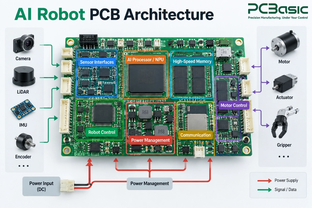
Think about what the robot needs to handle
simultaneously while it is running? The camera continues to feed back images,
LiDAR scans the surrounding environment, and the IMU and encoders provide
motion data on a constant basis. These pieces of information must be swiftly
supplied to the AI processor for processing, and the results must be
transmitted to the robot control board so that the robot knows what to do next.
At the same time, the motors are not stopping.
Starting, accelerating, braking, turning - all these actions cause the power
demand to constantly change. That is to say, within a robot with a limited
space, computing, sensing, control, and power supply are almost all happening
simultaneously.
|
Area
|
Conventional
Robot PCB
|
AI Robot
PCB
|
|
Computing
|
Based on MCU control
|
AI processor + high-speed memory
|
|
Sensor Data
|
Basic sensor inputs
|
Cameras, LiDAR, IMUs, encoders
|
|
Data Processing
|
Mainly processes control instructions
|
Real-time perception and AI inference
|
|
Power Demand
|
Relatively predictable
|
AI computing + changing motor loads
|
|
Board Interaction
|
Various functions may be relatively
independent
|
Computing, sensing, power supply, and motion
control are closely coordinated
|
This is an important difference between AI
robot PCB assembly and conventional robot PCB assembly: The difficulty does not
lie in simply adding more components, but in enabling different types of
circuits to coexist stably within a limited space. High-speed processors,
sensitive sensor circuits, and robot power PCB have different requirements for
signals, power, and heat dissipation.
For robotics PCBs this means that we can no
longer view a single function in isolation. If one part fails, then it could
affect the whole robot's sensing or movement.
As a result, AI robotics PCB
manufacturing calls for closer attention to how these functions interact. And the most common
challenges that arise during subsequent PCB assembly and testing are precisely
these impacts.
Which Assembly Challenges Become
More Critical in AI Robots?
When AI robot PCB enters the production stage,
the complexity of the design will soon be reflected in the manufacturing
process. More densely packed components, higher power consumption, high-speed
signals, along with constantly changing motor loads, will all bring new
challenges to assembly.
High-Density
Assembly Leaves less space for Error
AI processors and high-speed memory often use
BGA or other fine-pitch packaging. The denser the devices, the smaller the pads
and spacing. The requirements for solder paste volume, placement accuracy, and
reflow soldering control in robot PCB assembly are also higher.
Some small process variation may not cause
problems on a simple control board, but on high-density AI boards, they may
result in solder bridges, open circuits, or poor solder joints. BGA also has a
drawback: the solder joints are hidden at the bottom of the package. Areas that
AOI cannot see often require further X-Ray inspection.
AI
Computing and Motors Have Very Different Power Needs
The AI processor needs continuous and stable
power supply, while the loads of motors and actuators change rapidly with
startup, acceleration or stall. Two completely different power demands can
occur in the same robot.
Therefore, the robot power PCB is not just
responsible for delivering power to various modules. If the current path,
grounding, decoupling and thermal design are not handled properly, changes on
the motor side may affect the processor or sensors, and the continuous working
AI chip may also cause local high temperatures.
A
Board Can Power on but Still Fail to Transfer Data Reliably
This is a common problem where you have high
speed signals and motor circuits in the same environment. There are cameras and
sensors feeding data. Beside them are the motor drivers, DC-DC converters and
other circuits constantly switching on and off.
For robotics PCB assembly, sometimes such
problems do not manifest as a complete circuit failure. The PCB can boot up
normally, but sometimes there are communication errors, data loss or abnormal
sensor readings. So, we cannot ignore the impedance control, grounding,
high-speed interface and manufacturing consistency of the connectors.

Remember,
the PCB Will be Installed in a Moving Machine
The PCB in the robot is not immobile like the
PCB on the test bench. Long-term vibrations, shock, temperature fluctuations,
connector forces, and larger components can all put more strain on the solder
joints and the robot PCB.
Therefore, after the robotic PCB assembly is
completed, "being able to power on" is only the first step. The more
practical question is: Can these solder joints, connectors, and mounted component
remain stable after the robot repeatedly moves?
How Should AI Robot PCBA Be Tested Before
System Integration?
Can a PCBA that has passed the visual
and soldering inspections be directly installed in a robot? Not always. Certain
problems only show up when the circuit board begins processing data and
managing motors; they cannot be found on the assembly line.
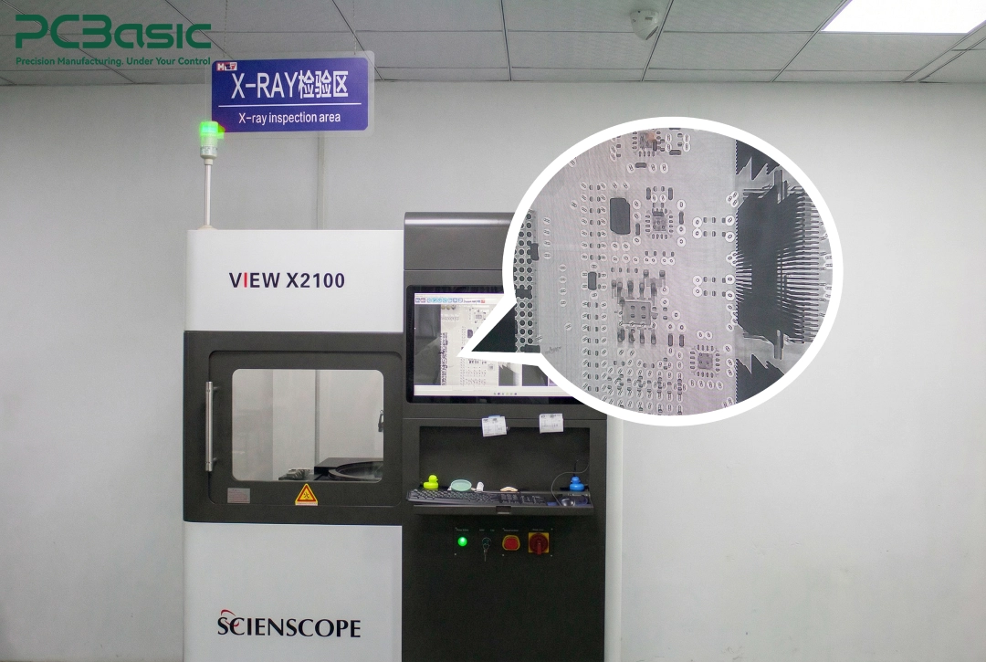
So, in AI robot PCB assembly, we usually start by checking the most
basic issues first. SPI checks the solder paste, AOI checks the components and
the visible solder joints, and BGA and other hidden solder joints are inspected
using X-Ray. Next, we look at the main power rails, check for any short
circuits, open circuits, and key connections to make sure the basic electricity
is working properly.
But this is just the beginning. Before we integrate the system, we also
need to check how it actually works:
• Sensor input: Can the data from cameras,
IMUs, encoders, etc. be continuously and reliably transmitted?
• Communication: Can the AI computing
board and the robot control board exchange data normally?
• Control output: Can the processed
instructions be correctly sent to motor drivers and other control circuits?
• Operation under load: Can the power
supply and signals remain stable when computing, communication, and sensors are
all working simultaneously?
Why do we need to
get to this point? Some PCBs might look fine at first and also work properly
when you turn them on. However, when several interfaces are working at the same
time, problems like communication errors, unreliable sensor readings, and unexpected
system resets can happen. These issues are hard to find just by using AOI,
X-Ray, or simple electrical tests.
For actual robot
projects, the testing process should be created according to the specific
product rather than sticking to a standard method. PCBasic can design functional testing fixtures based
on the testing requirements, programs, and interfaces provided by the customer
to verify the actual functions such as sensor input, communication interfaces,
and control outputs.
There is another issue that is often
overlooked: how to test. It is best to decide this before the production
process begins. In robotics PCB assembly, if test points, programming or JTAG
interfaces have been reserved during the design phase, and the connection of
the functional test fixtures has been considered, the later testing and
troubleshooting will be much simpler.
During mass production, the test results should
not simply disappear after a Pass or Fail decision The results should be
correlated with the specific PCB or production batch. If similar sensor,
communication or power supply issues arise later, we can refer to the records
and compare the data to quickly identify where the problem begins.
How Do You Move an AI Robot PCB from Prototype
to Production?
If a prototype functions properly, it indicates
that the design is basically feasible. However, this does not mean that every
single board during mass production will maintain the same performance.
In the early stage of AI robot PCB assembly, we
first confirm the operation of the processor, thermal performance, sensor and
motor control interfaces, as well as the normality of the actual assembly
through a prototype. Once the prototype is stable, the project usually needs to
go through pilot build rather than directly entering mass production.

At this point, our focus also changes: it is no
longer just "Can this board work?", but "Can the next batch
still be made the same way?"
During the pilot build, several things need to
be determined:
• BOM: Confirm the quantity of raw materials and the approved alternatives.
• Production process: Lock down the already verified assembly and testing methods.
• Revision control: Ensure consistency among Gerber files, BOM, firmware, and test
files.
• Pilot feedback: Based on the actual production and testing results, complete
necessary adjustments before mass production.
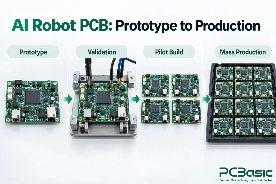
The entire process can be summarized as:
Prototype → Validation → Pilot Build → Mass Production
PCBasic can provide continuous support for the
project from DFM, component sourcing to SMT assembly and THT assembly, enabling the AI
robotics PCB manufacturing to smoothly transition from prototypes to stable
production.
For robot PCB assembly, the goal of mass
production is not to just produce one good board, but to ensure that the next
batch and the batch after that can be produced stably.
Conclusion
The challenges in
AI robot PCB assembly go beyond just putting more complicated components onto
the PCB. The real challenge is whether the whole board can keep working
smoothly when AI processing, sensors, motors, and communication systems are all
active at the same time.
This is also an
important aspect that both robot PCB assembly and robotics PCB assembly should
pay attention to. From creating initial designs to full-scale manufacturing,
the main question we're trying to answer is: Can this PCB carry out its
functions reliably and without issues in a real robot for a long period of time?
Developing AI robots for PCB? Send Gerber files,
BOM and assembly requirements to PCBasic, and we can discuss the next steps
based on your project needs.
FAQs
Q1: What is different about AI robot PCB
assembly?
AI robot PCB assembly combines AI computing,
sensors, communication, and motion control, creating higher demands for power,
thermal management, signal integrity, and assembly.
Q2: What does a robot control board do?
A robot control board connects sensors,
processors, motor drivers, and other subsystems to manage robot control and
communication.
Q3: Why is the robot power PCB important?
A robot power PCB supplies and manages power
for processors, sensors, motors, and other circuits, especially when motor
loads change quickly.
Q4: Can robotics PCB assembly support both
prototypes and production?
Yes. Robotics PCB assembly can support
prototypes, pilot builds, and volume production with consistent BOM,
manufacturing, and testing processes.