Global high-mix volume high-speed PCBA manufacturer
9:00 -18:00, Mon. - Fri. (GMT+8)
9:00 -12:00, Sat. (GMT+8)
(Except Chinese public holidays)
Global high-mix volume high-speed PCBA manufacturer
9:00 -18:00, Mon. - Fri. (GMT+8)
9:00 -12:00, Sat. (GMT+8)
(Except Chinese public holidays)
HomePage > Blog > Knowledge Base > Arduino Nano Pinout: A Beginner-Friendly Guide
If you’ve ever tried an Arduino Nano, you’ll realize it’s very small and fits easily in your hand. However, don’t underestimate it because of its tiny size. Inside that small board is everything you require to make your electronics projects work.
In this guide, we’ll go into detail about the Arduino Nano pinout, its physical design, dimensions, and what each pin is used for. If you’re just starting with Arduinos or want to know more about this particular model, this post will explain everything in a way anyone can understand. Read on to get all the details you need.
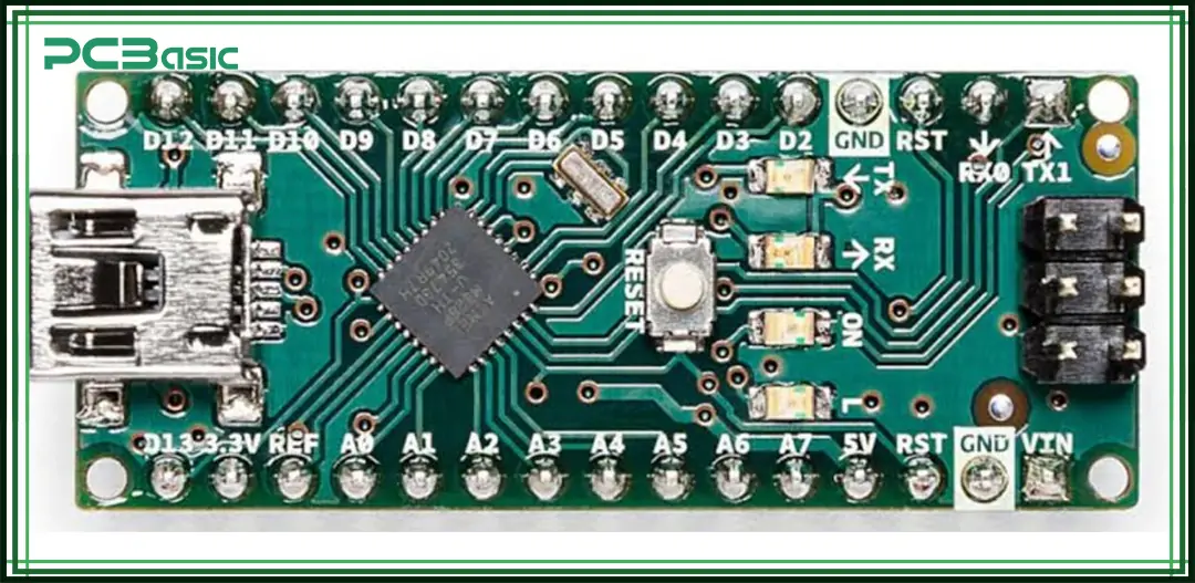
In spite of its tiny design, the Arduino Nano does a lot more than many other Arduino boards. With a microcontroller called the ATmega328P, the board is able to do things like blink an LED as well as run a complete sensor network.
The reason most people prefer Nano is that it’s the perfect size for breadboard use. This is why it’s perfect for situations where a regular Arduino Uno is too large.
Even though it is small, the Arduino Nano includes plenty of features.
• It has 14 digital I/O pins (6 of them can be used for PWM)
• 8 analog inputs
• 16 MHz clock speed
• USB Mini-B port
• 32 KB flash memory
In essence, it does almost the same things as an Arduino Uno, only in a smaller package. Because of this, it is ideal for small projects such as wearables, smart homes and portable sensors.
It’s also great because you can use it with either a USB or an external voltage source. That will be discussed soon. Right now, let’s focus on how the board is shaped and built.
When people call Arduino Nano the smallest Arduino, they’re not exaggerating.
• Length: 45 mm
• Width: 18 mm
• Height (with pins): 7–8 mm approx.
This compact size is what makes it breadboard-friendly. You can slot it right into a breadboard and still have space on either side to wire things up. That’s a big deal when you’re prototyping.
The Nano has two rows of header pins, 15 on each side, giving you access to all its digital pins, analog pins, and power lines. And it has a Mini-USB port on one end, which is used both for programming and power.
Here's a breakdown of how the pins are laid out on the board.
• One side: Digital pins (D0 to D13).
• Other side: A0 to A7 (Analog inputs), power pins (GND, 5V, 3.3V, VIN, etc.).
• Reset the button near the USB port.
• ICSP (In-Circuit Serial Programming) header for low-level flashing (if needed).
And one more thing—if you flip the board over, you’ll see the actual ATmega328P chip soldered directly onto the board. This means the Nano isn’t socketed like some larger Arduino boards, which contributes to its low profile.
Now that you have an idea of how the board looks and feels, it’s time to focus on the real heart of the Nano—its pinout.
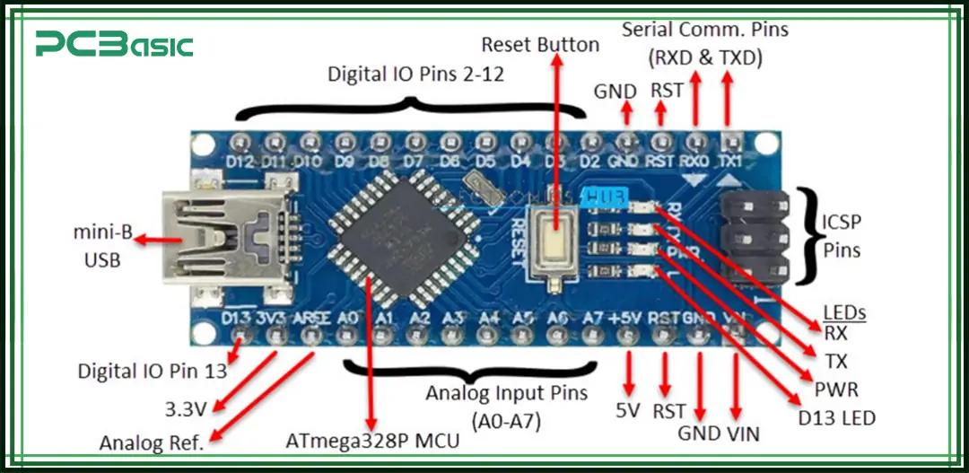
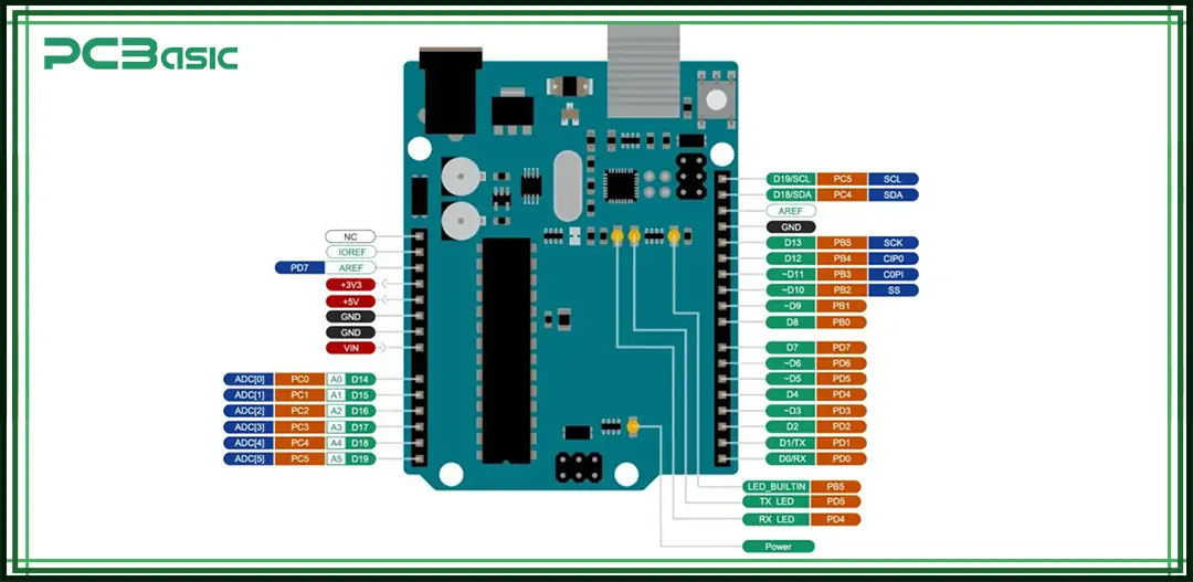
If you're building anything with the Nano, understanding its pin layout is non-negotiable. You can’t plug in sensors, displays, or relays without knowing what each pin actually does. So here’s a breakdown that keeps it simple.
You’ve got 14 digital I/O pins. These can be used as either input or output. You define this in your code with pinMode(pin, INPUT/OUTPUT).
Some of them have extra powers:
• PWM pins: D3, D5, D6, D9, D10, and D11 can do Pulse Width Modulation. Think of dimming LEDs or controlling motor speed.
• Serial Communication: D0 (RX) and D1 (TX) are used for communication between the Nano and your computer or another device.
• SPI Pins: D10 to D13 are also used for SPI (we’ll talk more about this later).
The analog pins are for reading sensors that give variable voltage. For example, temperature sensors or potentiometers.
• A0 to A5: It can also be used as digital pins if you run out.
• A6 and A7: These are analog inputs only. You can’t use them as digital I/O. They’re exclusive to the Nano (Uno doesn’t have these).
These analog inputs read values between 0 and 1023 by default, thanks to the onboard ADC (Analog-to-Digital Converter).
• 5V: This is a regulated 5-volt output. You can use it to power small modules.
• 3.3V: Useful for modules that work on lower voltage, like certain sensors.
• VIN: Feed in a voltage (7–12V typically) here if you’re not using USB.
• GND: This is the ground pin. You’ll use this a lot.
• AREF: Advanced users can use this to set a custom voltage reference for analog readings.
There’s also a reset pin. It does exactly what you think—resets the board. It’s the same as pressing the physical reset button.
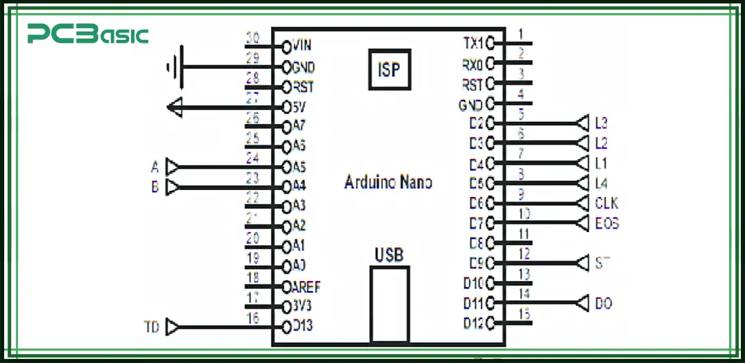
If you're the type who likes to know how things work under the surface, the Arduino Nano schematic is worth a peek.
At its core, the Nano uses the ATmega328P microcontroller. This chip is the brain of the board. It handles everything from controlling the pins to running your sketch.
But beyond the chip, there’s a lot more happening:
• Voltage Regulator – It takes in a higher voltage (like 9V from a battery) and drops it down to 5V for the board.
• Mini-USB to Serial Converter (CH340 or FT232) – This chip is what lets your computer talk to the Nano over USB. Note: Official boards usually use FT232; clones mostly use CH340.
• Crystal Oscillator – Keeps the board ticking at 16 MHz.
• Capacitors, resistors, and LEDs – These are scattered across the board to filter signals, pull pins up/down, or just give visual feedback.
The schematic isn’t just for engineers. If you ever plan to make your own version of the Nano or troubleshoot a faulty one, the schematic becomes your roadmap.
You can find the official schematic on Arduino’s website or on GitHub. Just search for “Arduino Nano schematic” and you’ll land on the datasheets you need.
One of the most common beginner mistakes is powering the Nano incorrectly. So, let’s keep it clear and simple.
There are three main ways to power your Nano:
The easiest and most common method. Just plug in a Mini-USB cable or a USB power adapter to your computer. The board gets 5V through the USB port.
• Good for prototyping
• No soldering or extra parts needed
• Also allows code uploading
If you're building a standalone project and don’t want to use USB, you can feed 7–12V into the VIN pin. The onboard regulator will convert it to 5V.
• Good for battery-powered projects.
• Use a 9V battery or DC adapter.
Note: Don’t supply 5V to VIN. The onboard regulator requires at least 7V input to function properly. So, 5V may result in unstable performance.
You can directly supply regulated 5V to the 5V pin if you know what you're doing. This skips the voltage regulator.
• Advanced users only.
• Be careful—no reverse polarity protection here.
Also, don’t forget the GND (ground) connection. Every circuit needs a return path.
 About PCBasic
Time is money in your projects – and PCBasic gets it. PCBasic is a PCB assembly company that delivers fast, flawless results every time. Our comprehensive PCB assembly services include expert engineering support at every step, ensuring top quality in every board. As a leading PCB assembly manufacturer, we provide a one-stop solution that streamlines your supply chain. Partner with our advanced PCB prototype factory for quick turnarounds and superior results you can trust.
Arduino Nano pins aren’t just for turning LEDs on or reading sensors. Some of them are dedicated to communication with other devices.
Here’s a breakdown of the three most important protocols:
• Pins: D0 (RX) and D1 (TX).
• Used for communicating with your computer or another serial device.
• Also, used when uploading code over USB.
Simple, reliable, and works out of the box.
• Pins: A4 (SDA) and A5 (SCL)
• Great for sensors, OLED displays, RTC modules, etc.
• Allows multiple devices to share the same two wires.
Many sensors today use I2C because it saves on wiring. You just need to assign each device a unique address.
• Pins: D10 (SS), D11 (MOSI), D12 (MISO), D13 (SCK).
• Faster than I2C but uses more wires.
• Good for things like SD cards or fast displays.
Each communication protocol has its pros and cons. SPI is faster, I2C uses fewer pins, and UART is easy to start with.
Pro tip: You don’t usually have to memorize which pins do what. The Arduino IDE libraries handle a lot of the heavy lifting.
There are quite a few Arduino models out there. So, how does the Nano compare?
|
Feature |
Nano |
Uno |
Mega |
|
Size |
Very small |
Medium |
Large |
|
I/O Pins |
22 |
20 |
70+ |
|
USB Port |
Mini-USB |
Type-B |
Type-B |
|
Breadboard Friendly |
Yes |
No |
No |
|
Ideal For |
Compact Projects |
General use |
Big Complex Projects |
The Arduino Nano size is one of its biggest selling points. It’s ideal for embedded projects where space is limited.
Compared to the Uno, the Nano offers almost the same functionality in half the space. The Mega is great for when you need tons of I/O pins, but it’s bulky.
So, if you're building a wearable, a compact sensor array, or just want to tuck your Arduino into a tight spot, Nano is the way to go.
When you start shopping for an Arduino Nano, you’ll notice something: there’s more than one kind.
Here are the main types you’ll come across:
• Made by Arduino.cc
• Uses ATmega328P
• Costs a bit more
• Reliable, high-quality
• A newer version
• Uses ATmega4809
• More RAM and flash
• Slightly different pin functions
• Includes Nano 33 IoT, BLE, and Sense.
• Come with Bluetooth, WiFi, and advanced sensors.
• Ideal for IoT and machine learning projects.
• Made by third parties
• Much cheaper (as low as $3)
• Often use CH340 chips instead of FT232 for USB.
• May need manual driver installation.
If you're a beginner or just prototyping, clones can save you money. However, for long-term reliability, the original Arduino board is a safer bet.
Tip: Always check reviews and make sure the pin layout matches the standard Nano before buying a clone.
The Nano may be small, but it works with a huge range of Arduino components. Here’s a short list of parts that pair well with it:
• LEDs – For simple outputs and status lights
• Push Buttons – For user input
• DHT11 / DHT22 – Temperature and humidity sensors
• OLED Displays – Compact 0.96” screens (use I2C pins)
• HC-05 Bluetooth Module – Great for wireless control
• Ultrasonic Sensors – For measuring distance
• Relay Modules – To control high-voltage devices
• Servo Motors – For movement-based projects
• IR Sensors – For remote control input
The Nano supports almost any Arduino parts compatible with the Uno, as long as the voltage and pin count are considered.
Because of its size, many Nano users prefer mini breadboards and male header pins for tight layouts.
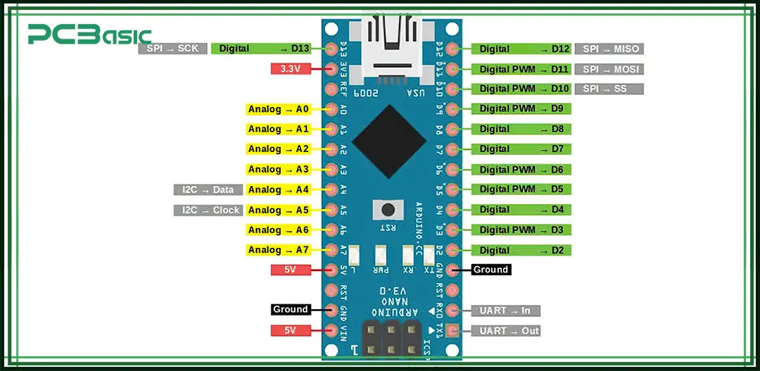
Let’s bring it all together with a full overview of the Arduino Nano pin layout.
Here’s how the 30 pins are typically arranged:
• D0 (RX): Serial receive
• D1 (TX): Serial transmit
• D2–D13: General I/O (some support PWM and interrupts)
PWM Pins: D3, D5, D6, D9, D10, D11
SPI Pins: D10 (SS), D11 (MOSI), D12 (MISO), D13 (SCK)
• A0–A5: Analog input (can also be used as digital)
• A4 (SDA) and A5 (SCL): I2C communication
• A6 & A7: Input-only analog (not digital-capable)
• VIN: External input voltage (7–12V)
• 5V: Regulated output
• 3.3V: Output from regulator
• GND: Ground (x2)
• RESET: Resets the board
• AREF: Analog reference voltage
• RST: Reset pin (same as reset button)
This layout makes the Nano flexible and powerful for a wide range of DIY electronics projects.
Pro Tip: For visual learners, download a colored pinout diagram—there are plenty online. You can even print it out and keep it near your workstation.
Even with dozens of Arduino boards available, the Arduino Nano remains a favorite. Because it's compact and affordable, moreover, it works with nearly all Arduino libraries and components.
Whether you're building a robot, a weather station, or a sensor-based system, the Nano fits almost anywhere. And with its strong community support, you'll never be short on tutorials, examples, and forums to help you out.
If you're getting started with Arduino or need something small and capable, the Nano might just be the smallest Arduino with the biggest potential.

Assembly Enquiry
Instant Quote


Phone contact

+86-755-27218592
In addition, we've prepared a Help Center. We recommend checking it before reaching out, as your question and its answer may already be clearly explained there.
Wechat Support

In addition, we've prepared a Help Center. We recommend checking it before reaching out, as your question and its answer may already be clearly explained there.
WhatsApp Support

In addition, we've prepared a Help Center. We recommend checking it before reaching out, as your question and its answer may already be clearly explained there.
