Global high-mix volume high-speed PCBA manufacturer
9:00 -18:00, Mon. - Fri. (GMT+8)
9:00 -12:00, Sat. (GMT+8)
(Except Chinese public holidays)
Global high-mix volume high-speed PCBA manufacturer
9:00 -18:00, Mon. - Fri. (GMT+8)
9:00 -12:00, Sat. (GMT+8)
(Except Chinese public holidays)
HomePage > Blog > Knowledge Base > PCB Switch: A Comprehensive Guide
In almost every electronic device, PCB switches play a crucial role. A PCB switch enables users to easily turn circuits on or off, change settings, or activate special functions. From simple gadgets to advanced computers, you can see circuit board switches being used for control and selection. There are many different types of PCB switches on the market, such as PCB tactile switches, PCB slide switches and PCB toggle switches. Each type of circuit board switch has its unique characteristics.
Next, in this article, we will introduce the most common types of circuit board switches. We will explain how they work and teach you how to design and integrate the appropriate PCB switches. Let's first understand what a PCB switch is.
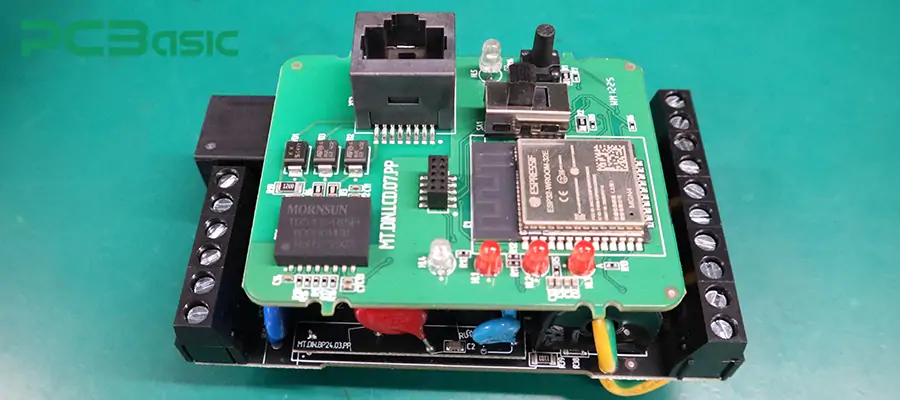
A PCB switch is an electronic switch component specifically installed on a printed circuit board. Its function is to control the current by pressing, pulling or sliding to connect or disconnect the circuit. That is to say, the PCB switch enables users to directly control the on/off, mode switching, reset and other functions of the device.
PCB switches are also called circuit board switches or circuit board buttons. This type of component is almost applied to all electronic products, such as remote controls, computer keyboards, audio equipment, industrial automation, household appliances, etc. These switches enable users to interact conveniently with various electronic devices.
Different PCB switches also vary in structure and performance. Some are designed to be very compact and suitable for portable devices, such as the small circuit board button. Some, such as PCB power switch, can withstand larger currents and are suitable for high-power applications. Most PCB switches support multiple assembly methods such as through-hole or surface mount (SMD), facilitating different PCB process requirements.
At present, there are various PCB switch types on the market, which can meet different circuit requirements. Common types include PCB tactile switch, PCB push button switch, PCB slide switch, and PCB toggle switch, etc. Choosing the right PCB switch is crucial for the stability, user experience and durability of electronic products. Below, we will introduce in detail several common types of PCB switches.
In circuit board design, there are many different types of PCB switches. Each circuit board switch has specific functions, feel and installation methods.
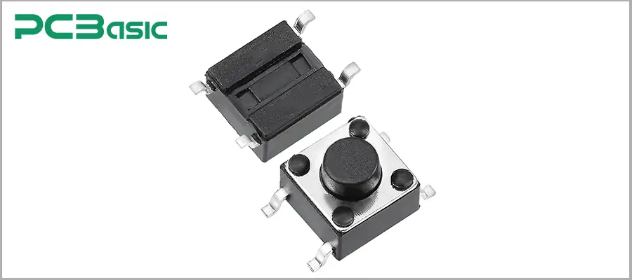
PCB tactile switch is a small, instantaneous circuit board switch that gives a crisp "click" sensation when pressed. It uses metal spring pieces inside to achieve circuit connection. The operation of this PCB switch is simple and reliable, and it is widely used in situations where obvious user feedback is required, such as keyboards, remote controls and handheld devices. They have two installation methods: surface mount and plug-in, and can be adapted to different PCB switch designs.
Main features
Small in size and ultra-thin design
Obvious tactile feedback
Instantaneous action (disconnection upon release)
Multiple installation methods are available
Application scenarios
The buttons on the calculator and the remote control
Control buttons on smart devices
The reset switch on the development board
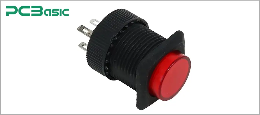
Push button switch is a common type of circuit board switch. Its structure is simple. Pressing it will connect the circuit, and releasing it will disconnect (or keep it connected, depending on the type). This type of switch can be either instantaneous or self-locking. The operation of push button switches is very intuitive and the key area is relatively large. It is highly suitable for use as a power switch, function switching or reset control device for equipment.
Push button switch usually has two installation methods: through-hole and SMD, which is convenient for adapting to various PCB switch design requirements. The key feel is solid, and users can clearly perceive whether the operation is effective. The rich selection of shapes and colors also makes it convenient to distinguish different functions on the panel or PCB.
Main features
The structure is simple and the key area is large
Supports two action modes: instantaneous and self-locking
The touch is clear and the operation is convenient
High durability, suitable for high-frequency operations
Application scenarios
Power or reset buttons for devices such as calculators and remote controls
The start and stop buttons on the industrial control panel
Function switching keys for household appliances and medical instruments
User input buttons on the development board and test equipment
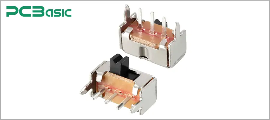
PCB slide switch is a circuit board switch that switches the circuit state by sliding the lever. Users only need to push the lever to switch between different switch positions to achieve the connection or disconnection of the circuit. The PCB slide switch is suitable for simple controls such as single-throw (SPST) and double-throw (SPDT), and can also be used for complex switching with multiple gears and multiple loops. PCB slide switches usually offer two installation methods: through-hole and SMD. Its sliding feel is smooth, and the position of the lever is clear, making it convenient for users to intuitively identify the current switch status.
Main features
The structure is simple, with sliding operation and distinct gears
Supports multiple pole numbers and gears (such as SPST, SPDT, DPDT, etc.)
The position is clear and easy to identify the current state
High reliability and suitable for high-frequency switching
Application scenarios
Selection of function modes for electronic toys and radios
Signal switching for industrial control and communication equipment
Switch Settings for smart home devices and portable devices
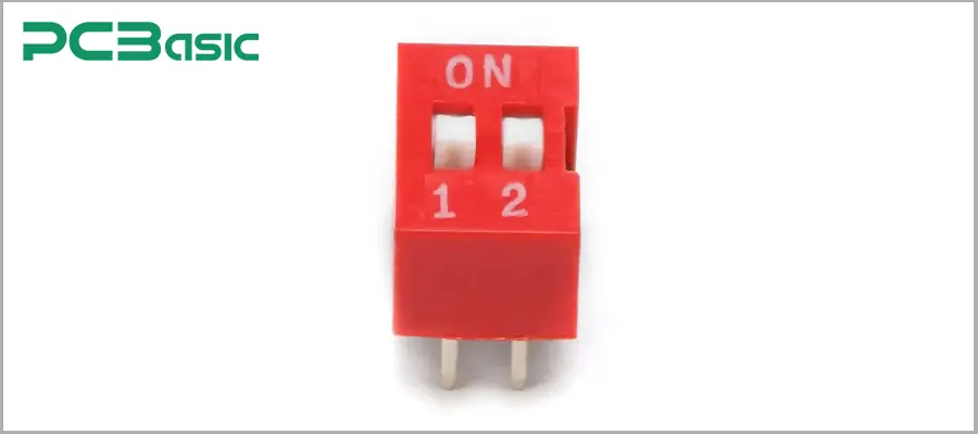
PCB DIP switch is a circuit board switch composed of multiple micro toggle switches. It usually appears in the form of a dual-in-line package (DIP). Each of its small switches can be independently toggle, and when used in combination, it can achieve various circuit configurations. Users can change the working status or configuration of the circuit board by manually towing each switch without the need for software operation.
PCB DIP switches are generally installed by through-hole method, and there are also some surface mount (SMD) products. It has a compact structure, occupies a small space, is easy to operate and has high reliability. Each small switch has a clear ON/OFF (ON/OFF) status indicator, which is convenient for users to identify and set.
Main features
Multiple micro-switches are integrated into one, facilitating batch settings
Supports multiple combinations and flexible configuration of circuit parameters
The operation is simple and the on/off status is intuitive
Compact structure, suitable for high-density PCB layout
Application scenarios
The address or function selection of communication equipment and network equipment
Parameter Settings of industrial automation equipment
Selection of working modes for intelligent controllers and development boards
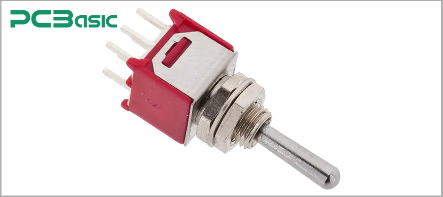
PCB toggle switch is a circuit board switch that switches the state of a circuit by toggling the handle. Users only need to pull the switch handle up and down or left and right to switch between different positions and achieve the connection or disconnection of the circuit. This switch is available in both instantaneous type (automatically resets after being pulled) and self-locking type (remains in the same state after being pulled). The structure is sturdy and the operation feel is clear. It is usually installed in a through-hole manner and is suitable for PCB switch designs that require high reliability in industries, communications, etc.
Main features
The lever structure ensures clear switching and distinct gear positions
Supports multiple pole numbers and gears (such as SPST, SPDT, DPDT, etc.)
There are two action modes: instantaneous and self-locking
Long-life design, suitable for frequent operation
Application scenarios
Function switching of the industrial control panel
Mode switching of communication equipment and instruments
Key parts such as power switches and main control switches
Manual control of various development boards and testing equipment
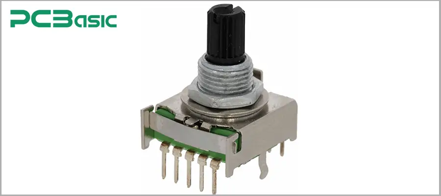
PCB rotary switch is a circuit board switch that achieves multi-gear switching through rotation operation. Users only need to rotate the knob of the switch to switch between multiple contacts or channels. This type of switch usually has multiple positions and pole numbers to choose from, and can be flexibly configured according to actual needs. PCB rotary switches are usually installed in a through-hole manner, and there are also some surface mount (SMD) products suitable for various PCB switch designs. Its rotation feels smooth, the gear position is accurate, it is highly durable and can maintain stable performance for a long time.
Main features
The knob can be rotated for switching, with multiple positions to choose from
Supports multi-pole and multi-position configuration, with flexible functions
The gears are clear and the rotation feels good
Stable and reliable, suitable for high-frequency switching requirements
Application scenarios
Input/output selection and volume adjustment of audio equipment
The function mode switching of the instrument and meter
Multi-channel signal selection for industrial equipment
Channel or parameter Settings for communication and test equipment
|
Switch Type |
Operation Method |
Feedback Type |
Action Style |
Typical Application |
Mounting Style |
|
PCB tactile switch |
Press |
Tactile (click) |
Momentary |
Keypads, remote controls |
SMD / Through-hole |
|
Push Button Switch |
Press |
Soft or firm |
Momentary/Latching |
Power/reset, control panels |
SMD / Through-hole |
|
PCB slide switch |
Slide (side-to-side) |
Position change |
Latching |
Mode selection, small devices |
SMD / Through-hole |
|
PCB DIP switch |
Flip lever (by finger) |
None/visual ON/OFF |
Latching |
Config settings, address setting |
Through-hole / SMD |
|
PCB toggle switch |
Flip lever (up/down) |
Firm lever feel |
Momentary/Latching |
Power, industrial control |
Through-hole |
|
PCB rotary switch |
Rotate knob |
Click/stop by detent |
Latching (multi) |
Function or channel selection |
Through-hole / SMD |
All PCB switches are controlled by connecting or disconnecting circuits. When you press, pull or rotate the switch, the contacts inside the switch will move. This change determines whether the current flows or is blocked.
Mechanical operation is the most common method. Most circuit board switches have metal contacts. When the PCB tactile switch or PCB push button switch is pressed, the metal contacts will come into contact with each other or separate, thereby achieving the connection or disconnection of the circuit.
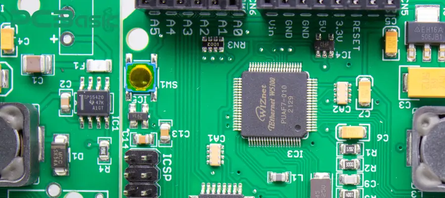
Another way is electrical operation. Some switches (such as PCB power switch) use electronic components or semiconductor devices for switching. This type of switch can be controlled to be on and off through electrical signals and is suitable for circuits with special requirements.
There are mainly two ways for switches to operate:
Momentary: The circuit is only connected when you press the switch. After releasing the hand, the switch automatically returns to the initial state and the circuit is disconnected. Most PCB tactile switches fall into this category.
Latching: After the switch is switched once, the circuit will remain in the current state. Only by operating the switch again will the state change. PCB toggle switch and PCB slide switch are commonly seen in this structure.
No matter what type it is, PCB switch enables users to conveniently control the on and off of circuits, thereby achieving various functional switches and mode selections.
To design and integrate a PCB switch on a circuit board, simply follow these steps:
1. Clarify the switch requirements.
First of all, we need to determine what functions the PCB switch is to achieve. For instance, is it necessary to switch between multiple gears? If necessary, the PCB rotary switch can be chosen. Because only by determining the specific application scenarios can the most suitable PCB switch type be selected.
2. Select and download the correct packaging and symbols.
Visit the official website of the switch manufacturer and download the schematic library symbols and PCB package (footprint) corresponding to the selected circuit board switch. This can ensure that the component size and the pads are exactly matched.
3. Make a reasonable layout and plan the routing.
In the PCB layout, place the PCB mount switch in a position that is easy for users to operate. Then, arrange the direction of the copper wires related to the switch reasonably. The connection distance should be shortened as much as possible to reduce interference and impedance.
4. Add openings or installation holes (if necessary).
For switch types that require panel operation or firm installation, such as PCB power switch, appropriate openings or screw holes should be reserved in the PCB design so that the switch can be firmly installed.
5. Check the electrical connections and clearances.
After completing the component layout, check whether all the switch pins are correctly connected to the circuit to ensure there is no short circuit. It is also necessary to confirm that there is sufficient space around the PCB switches to facilitate subsequent operations and maintenance.
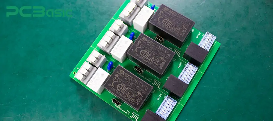
6. Prepare for assembly and testing.
After the PCB production is completed, functional tests are conducted on all circuit board buttons to ensure that each PCB switch is firm, reliable and working properly.
By following the above six steps, you can integrate various PCB switches on the circuit board efficiently and reliably.
PCB switches are indispensable core components in electronic design. A thorough understanding of various types of PCB switches helps us select the most suitable circuit board switches for different applications. During the design and integration process, choosing high-quality PCB switches and following standardized installation and layout principles can effectively enhance the stability and reliability of the product. I believe that after reading this article, you must have a deeper understanding of PCB switch!
 About PCBasic
Time is money in your projects – and PCBasic gets it. PCBasic is a PCB assembly company that delivers fast, flawless results every time. Our comprehensive PCB assembly services include expert engineering support at every step, ensuring top quality in every board. As a leading PCB assembly manufacturer, we provide a one-stop solution that streamlines your supply chain. Partner with our advanced PCB prototype factory for quick turnarounds and superior results you can trust.

Assembly Enquiry
Instant Quote
Phone contact

+86-755-27218592
In addition, we've prepared a Help Center. We recommend checking it before reaching out, as your question and its answer may already be clearly explained there.
Wechat Support

In addition, we've prepared a Help Center. We recommend checking it before reaching out, as your question and its answer may already be clearly explained there.
WhatsApp Support

In addition, we've prepared a Help Center. We recommend checking it before reaching out, as your question and its answer may already be clearly explained there.
