As the electronics industry becomes increasingly globalized, effective communication across international borders is essential for ensuring high-quality, cost-effective production. However, differences in design rules, documentation standards, and technical language have historically posed challenges to international collaboration.
Since its establishment in 1957, the Institute for Interconnecting and Packaging Electronic Circuits (IPC) standards have evolved over decades. It has a crucial role in keeping pace with technological advances while remaining the definitive set of rules governing PCB manufacturing worldwide. Compliance with IPC specifications is now mandatory for any company participating in the international electronics trade.
By its 60th anniversary in 2017, IPC had over 4000 member sites across 79 countries worldwide. Read on as we give you an overview of the IPC standards for PCB design documentation. We'll also discuss how their guidelines have helped streamline processes for companies with factories and suppliers in multiple countries.
What are IPC and IPC Standards for PCB
So, what does IPC stand for in electronics? Well, it is The Institute for Interconnecting and Packaging Electronic Circuits– formerly known as the Institute for Printing Circuits. This is a global trade association that develops standards for electronics manufacturing and assembly. Founded in 1957 and based in Bannockburn, Illinois, IPC works to develop standard processes and documents in the fields of electronic design, assembly, fabrication, and finishing of printed circuit boards and printed electronics.
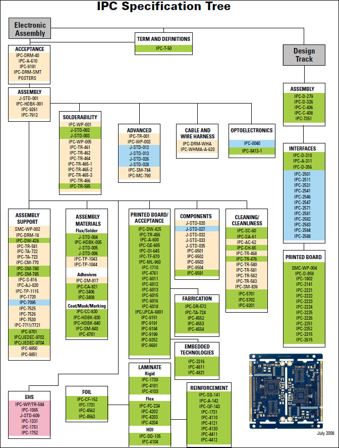
IPC standards enable companies to effectively communicate design needs and production requirements to partners globally. The standards provide common documentation to facilitate understanding and consistency across organizations. Some key areas covered by IPC standards include packaging, assembly, materials, electronics manufacturing, and terminology. Regularly updated standards ensure that processes and documentation stay at par with the latest technologies and best practices.
These IPC standards are developed through a consensus process that involves input from industry leaders, academic institutions, government agencies, and other interested groups. The consensus-based development helps ensure the standards represent practical realities of the design and manufacturing landscape. IPC standards are voluntary but are widely adopted worldwide due to their usefulness in streamlining processes for electronics manufacturing.
Adherence to IPC standards can help companies reduce costs through more efficient vendor communication, avoidance of defects and rework, and smoother transitions when changing suppliers or partners. The standards provide consistent guidelines that electronics manufacturers, technology developers, educational institutions, and students can rely on.
IPC continues to develop new standards and update existing ones to address emerging technologies and the needs of the rapidly innovating electronics industry. Its standards have become critical reference points for the global electronics design and manufacturing ecosystem.

Type of Standards in PCB and PCBA Manufacturing
PCB and pcba manufacturing involves complex techniques, tools, and skills to fabricate a high-quality circuit board. Those techniques follow standards and procedures to ensure high-quality end products every time.
IPC PCB standards are well-known standards most manufacturers follow according to customers’ requirements and demands. However, there are other standards that we should be aware of when we proceed to manufacture our PCB or PCBA:
· International Organization for Standardization or in short, ISO – is a collection of standardized processes to ensure the facility, organization, warehouse and other factory key points stand according to the industry standards. ISO comes in numbers such as ISO 9001:2015, 14001:2015, etc. The first number indicates the standard ID, while the second shows the release date.
· International Telecommunication Union authority, or short “ITU,” – controls the quality and standards of telecommunication equipment.
· International Electrotechnical Commission, “IEC” in short – helps us to verify and control the quality of electronic and electrical appliances. Verification is done through various electrical certifications that ensure safety and quality.
While in this article we mainly discuss the benefits of IPC standards, it’s crucial to be aware other standards exist and how they can benefit the field of PCB and PCBA manufacturing.
Development of IPC Standards
The development of IPC standards has been a remarkable journey that parallels the rapid evolution of the electronics industry itself. These standards have played a pivotal role in ensuring the reliability, quality, and interoperability of electronic components and printed circuit boards (PCBs).
Let's take a look into the fascinating history of IPC standards, tracing their evolution through key milestones and developments.
Early Years: 1950s-1970s
The origins of IPC standards date back to the 1950s, when the electronics industry began to evolve rapidly. In 1958 – a year after it was founded, IPC published its first electronic packaging standards to establish common design rules and materials for circuit boards. Titled "How to Design and Specify Printed Circuits," the book sold over 25,000 copies successfully.
Through the 1960s and 1970s, IPC worked with industry to create drawings, test methods, and material specifications to support increased complexity in printed circuit board and electronic assembly design. The Acceptability of Printed Boards (IPC-A-600), published in 1964, particularly sets the foundation for the IPC standard for bare PCB acceptability requirements. This helped drive early growth and innovation.
Advancing Technology: 1980s-2000
As surface mount technology emerged in the 1980s, IPC drove the standardization needed to enable the dense, fine-pitch component placement this innovation required. Standards for land pattern designs, manufacturing processes, and reliability testing aided widespread adoption.
Into the 1990s, IPC collaborated on interconnect format specifications and environmental tests vital for expanded use of plastics and lead-free and no-clean assembly. These efforts supported the miniaturization underpinning each new generation of electronics.
Proliferation and Beyond: 2000s-Present
Over the past 23 years, IPC has released over 300 standards covering electronics assembly, microelectronics, productive interconnection technologies, and related supply chain processes. Emerging areas like flexible hybrid electronics, 3D and additive manufacturing, and sustainability also have IPC standards.
With the tremendous growth of the global electronics industry, IPC's consensus-based standards development process and diverse membership have become invaluable to ensure interoperability, quality, and continuous improvement across the entire electronics manufacturing ecosystem.
Why Do IPC Standards for PCB Design Matter
Interconnecting electronic components through printed circuit boards (PCBs) has allowed for the rapid advancement of technology over the past few decades. However, with increased complexity, standardization is needed to maintain quality, reliability, and interchangeability. IPC standards help ensure PCB design, manufacture, and assembly meet industry-agreed-upon criteria.
Here are five key reasons why following IPC standards for PCB design is important.
Reliability and Long Product Lifetimes
IPC standards specify tolerances and design guidelines that have undergone extensive testing to withstand repeated stresses during expected product lifecycles. Adhering to these standards helps prevent defects that could cause connectivity failures over the operating lifetime of devices in the field.
Compatibility Across Companies
Compatibility between different components and systems from various manufacturers is essential for high-volume electronic manufacturing. IPC standards promote compatibility by establishing common rules for how PCBs and components should interface physically and electrically. This allows PCBs made by different fabricators to integrate and work
seamlessly together on assembly lines.
Quality Through Process Discipline
Implementing IPC specifications provides manufacturing discipline that supports continuous quality improvement efforts. The standards define quantified acceptance criteria for attributes like solderability, plating thickness, and resistance to thermal shock. This enables easy verification that quality requirements are consistently met from lot to lot.
Safety from Electrical Hazards
IPC standards include guidelines for preventing electrostatic discharge and minimizing other electrical risks, which become increasingly important as circuit densities rise. Following safety standards gives customers confidence their boards won't unexpectedly fail or cause reliability issues due to electrostatic discharge or other electrical problems.
Yield Through Reduced Rework
Reworking defective boards drives up costs, so preventing failures early in the design and fabrication stages is important. IPC standards lower manufacturing risk by defining design and process best practices. PCBs made per IPC specs have fewer problems passing electrical testing and inspection, improving overall yield and operational efficiency.

Why IPC Standards Should You Apply for PCB Design
When designing printed circuit boards (PCBs), it is crucial to adhere to established industry standards to ensure quality, reliability, and manufacturability. The IPC sets the leading standards for PCB design and manufacturing.
These are some of the key IPC standards that every PCB designer should follow.
IPC-A-600: Acceptability of Printed Boards: This standard outlines the minimum requirements for PCB quality, reliability, and performance. It covers all aspects of board construction, including finished board thickness, plating thickness, copper weight, hole quality, and more. Following IPC-A-600 helps to produce boards that pass structural and environmental reliability testing.
IPC-2222: Cable Harness Design Guide: The IPC-2222 standard guides the design and development of electrical cable harnesses and wiring assemblies. It covers topics such as wire and cable selection, connector specification, routing, termination, labeling, and documentation. Following the guidelines in IPC-2222 helps ensure harness designs can be manufactured reliably and assembled with minimal rework. The PCB standards also promote designs that simplify testing and verification.
IPC-D-275: Design Standard for Rigid Printed Boards and Rigid Printed Board Assemblies: This standard establishes guidelines for PCB layout functions like component and line spacing, pad sizes, footprint definitions, routing clearances, and stack heights. Adhering to IPC-D-275 design rules ensures manufacturability on modern assembly equipment and improves yields. It also promotes thermal and mechanical reliability.
IPC-2221: Generic Standard on Printed Board Design: IPC-2221 is considered the most comprehensive set of design rules, incorporating the requirements from numerous other IPC standards. It establishes detailed design practices for everything from stack-up definition to design for manufacture (DFM) guidelines. Strict compliance with IPC-2221 gives high confidence that boards will be producible and functional.
IPC-A-610: Acceptability of Electronic Assemblies: This standard covers assembly quality and workmanship criteria. It is used to inspect assembled boards to guarantee acceptable soldering, component placement, and overall quality of manufacture. Certification to IPC-A-610 assures that boards and assemblies will perform reliably.
IPC-1791: High Reliability/Long Life PCB Design: The IPC-1791 standard defines rigorous requirements for designing PCBs for long service life in harsh and reliability-critical applications like aerospace, medical, and military. It covers elevated temperature storage and operation, thermal cycling tolerance, shock/vibration hardening, and component derating/failsafe requirements.
IPC-6012: Qualification and Performance Specification for Rigid Printed Boards: This IPC standard for PCB specifies test methods and acceptance criteria for key PCB performance characteristics like dimensional stability, solderability, copper peel strength, thermal shock, and moisture resistance. It is used to qualify boards for high-reliability use and identifies any latent defects from the fabrication process.
IPC-D-275: Design Standard for Rigid Printed Boards and Rigid Printed Board Assemblies: These PCB standards cover PCB dimensions and tolerances, layer stack-up definitions, design layout methodology, component placement rules, and fabrication drawings/documentation requirements. It aims to ensure dimensional accuracy and repeatability of design features between multiple board houses.
IPC/WHMA-A-620: Requirements and Acceptance for Cable and Wire Harness Assemblies: This standard pertains to wire harness and cable assembly manufacturing. It defines workmanship and quality criteria for wire preparation, termination, and joins/splices. Following this standard helps verify harness assemblies have been built to specifications and will perform reliably.
IPC J-STD-001: Requirements for Soldered Electrical and Electronic Assemblies: This specification sets process and acceptance criteria for soldering electronics assemblies. It covers topics like soldering methods and equipment, qualifications of materials and processes, and quality attributes like solder amount and bridging. Compliance ensures proper soldering practices are followed.

What Do IPC Classes Mean?
The IPC classifies printed circuit boards into three categories based on their quality levels - Class 1, Class 2, and Class 3, with Class 3 being the highest quality standards. IPC established this classification system under the IPC-6011 standard to define different levels of quality for electronics manufacturing.
One of the key differences between the classes lies in the degree of inspection and testing electronics assemblies must go through, plus the quality standards they adhere to. Understanding each class and its specific requirements can help OEMs determine which class suits their product. Factors such as customer needs and costs significantly influence the selection of a class.
Here is an overview of the IPC class definitions and some guidance on when each class should be considered:
· Class 1 boards are intended for general electronics products with basic functional requirements.
· Class 2 boards are meant for dedicated service electronics with increased quality demands.
· Class 3 boards are targeted for applications requiring high reliability, like medical devices, and are held to the strictest quality controls.
Let's take a closer look at each of them.

Class 1 Electronics: General Electronics Products
The first electronic products class includes boards intended for lower-cost consumer goods with expected lifespans of only a few months or years. These devices prioritize short-term affordability over longevity.
Think of a children's toy - while the lights and sounds may work perfectly for months of playtime, the low-quality components, simplified designs, and lack of rigorous testing. This means parts are likely to stop functioning after just a year or two of normal use at most. Repairs would not be cost-effective, given the low price point.
Class 2 Electronics: Dedicated Service Electronics Products
Class 2 covers a wide range of electronic devices for both personal and commercial use where continuous operation is expected for extended periods. They include things like:
· Home appliances
· Entertainment systems
· Industrial controls
· Consumer electronics
While unscheduled downtime would lead to frustration or lost productivity, failures would not pose safety risks or severe disruptions. To ensure dependable performance throughout the intended lifespan, Class 2 boards utilize higher-grade components and more stringent manufacturing processes than Class 1. However, specifications still need to match the rigorous standards for mission-critical applications.
Class 3 Electronics: High-Reliability Electronics Products
Class 3 PCBs are intended for mission-critical applications where high reliability is essential for safety, business operations, or national security. This includes:
· Avionics
· Military systems
· Lifesaving medical devices
· Network infrastructure equipment
Boards are designed to withstand the harshest environmental conditions during operation and storage, meeting requirements for moisture resistance, thermal cycling, mechanical shock, and environmental testing. Only the best quality, most durable components are used.
Standards like IPC-A-610 require rigorous manufacturing and quality control processes. This helps minimize defects and ensure long operational lifetimes, even in extreme moisture, vibrations, temperature swings, and other stresses.
IPC Terminology You Should Know
When designing and manufacturing printed circuit boards (PCBs), there are numerous terms specific to the IPC standards that are important to understand. A solid grasp of this terminology will allow the best communication between all parties involved in a PCB project.
Netlist
A netlist is a fundamental concept that describes the interconnectivity between various components on a PCB. It lists explicitly each "net" or connection between two or more points on the board. Engineers will design and test a circuit using a netlist before proceeding to layout.
Trace
A trace refers to a conductive path that transports signals or power between components. Traces are typically copper lines formed on internal layers during manufacturing. Their width and spacing are specified in mil (thousandths of an inch). IPC classifications determine minimum allowable trace widths and spacings based on a board's intended complexity and component density.
Plated-Through Hole (PTH)
Board features like holes, slots, and cavities are collectively known as plated-through holes or PTHs. During fabrication, the walls of these openings will be plated with conductive material like copper. This allows for interconnectivity between layers. PTHs primarily enable vertical connection of components.
Blind Via and Buried Via
In addition to PTHs, multilayer boards employ blind and buried vias to route signals between layers. Blind vias only connect outer layers, while buried vias pass through internal layers. IPC standards specify the diameter, wall thickness, and drill angles/tolerances for vias.
Solder Land
Components must terminate their lead systems on designated lands surrounding a PTH or pad for soldering. The land pattern dictates the size, shape, and pitch of these assembly points. IPC establishes land requirements to prevent opens or solder bridges while optimizing board space and test/rework capabilities.
Solder Mask
Solder mask is an insulating coating that covers non-conductive areas of the board. It protects copper circuitry from oxidation and prevents accidental shorts. Depending on a board's function and needs, IPC standards establish attributes for solder mask color, thickness, curing, and more.
Conformal Coating Preparation
Preparing a board for a conformal protective coating involves thoroughly cleaning flux residues per IPC specs. This prevents degradation of the seal over time. Coating thickness and dielectric strength must also meet IPC standards.
Annular Ring
The annular ring refers to the conductive ring surrounding a plated through-hole on inner layers. IPC specifications define minimum annular ring widths to ensure adequate bonding between a plated wall and copper pad.
Solder Joint
The solder joint is where solder forms the mechanical and electrical connection between a component's termination and the PCB. IPC standards provide categories for acceptable solder joint forms based on factors like wetting and fillet size.
Time, Temperature, and Solder Type
As outlined in IPC standards, the reflow soldering process involves defined parameters of time, temperature, and solder composition. Proper reflow is crucial to achieving acceptable solder joints and maximizing yield.
HEPA and Ionized Air
Per IPC requirements, manufacturing areas dealing with unpacked boards must employ HEPA filtration and ionized blow-off air to maintain stringent cleanliness levels. This prevents defects from particles during assembly and processing.
Coupon
Periodic sample coupons are required for process verification as boards pass through various fabrication stages. IPC standards mandate what tests coupons must undergo and how results must be documented and approved to ensure process control.
Understanding these key IPC terminology terms related to design, fabrication, assembly, and finishing will enhance communication and catch issues early in a PCB project cycle.
PCBasic's Commitment to IPC Standards
PCBasic has demonstrated an unwavering commitment to meeting and exceeding IPC standards for over a decade. As one of the earliest adopters of the IPC acceptance criteria, we have implemented stringent checklist-driven quality control processes that have become common practice across our industry today. Our state-of-the-art automated optical inspection systems and technical staff trained directly by IPC perform thorough pre- and post-production validation of every board to the most current standards.
Beyond just compliance, however, we strive to be leaders and partners in the ongoing development of specifications themselves. Our engineers have contributed meaningfully to several working groups over the years, providing feedback from the manufacturing floor that helps evolve guidelines to match emerging technologies and capabilities. It is through this two-way collaboration that standards truly progress to benefit all.
Reliability is a core value at PCBasic, and we recognize IPC standards as the engineering benchmark that ensures consistent, predictable performance for our customers. Our customers can trust that every board leaves our facility meeting the industry's 'golden rules' for quality, functionality, and longevity. Whether in the highly regulated medical sector, safety-critical automotive applications, or cutting-edge aerospace programs.
If you demand absolute assurance that your boards perform as designed throughout their life cycles, look no further than PCBasic. Contact us today to discuss how our investment in IPC-centered manufacturing processes can help bring your next product to market with confidence. Your satisfaction is our primary goal.
Looking for a PCB & PCBA quote? Contact us now.


