Global high-mix volume high-speed PCBA manufacturer
9:00 -18:00, Mon. - Fri. (GMT+8)
9:00 -12:00, Sat. (GMT+8)
(Except Chinese public holidays)
Global high-mix volume high-speed PCBA manufacturer
9:00 -18:00, Mon. - Fri. (GMT+8)
9:00 -12:00, Sat. (GMT+8)
(Except Chinese public holidays)
HomePage > Blog > Knowledge Base > Circuit Board Wiring: How do we do it?
Circuit board wiring is the core of all electronic products. Whether it is a simple circuit board or a complex circuit board system, such as furnace circuit board wiring, a good wiring design is the key to ensuring the performance and stability of electronic products. Wiring directly determines whether the circuit board can operate normally, determines the connection mode between components, and more profoundly affects signal quality, electromagnetic compatibility and the manufacturability of the final product.
Next, this article will take you through a comprehensive understanding of the basic knowledge of circuit board wiring, common wiring types, material selection, layout techniques, wiring standards, and solutions to common problems. At the same time, we will also explore the practical role of wiring in the PCB assembly process. Hope this can help you achieve a more efficient and reliable circuit board design and assembly in your project.

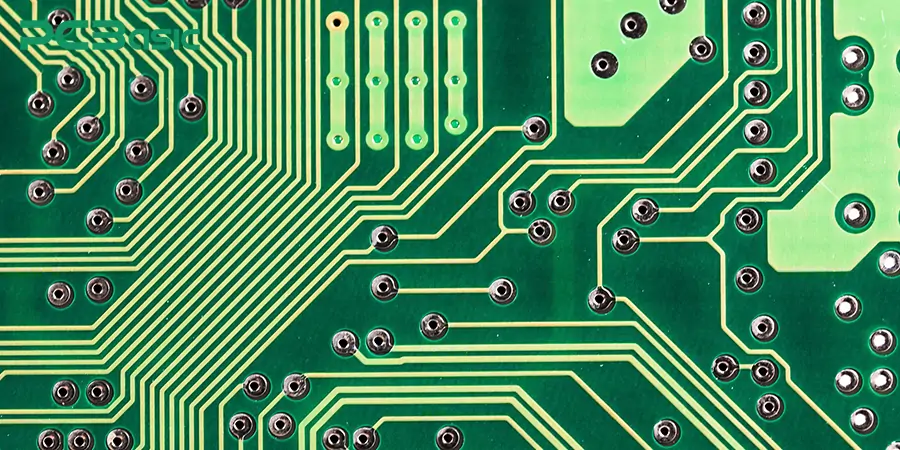
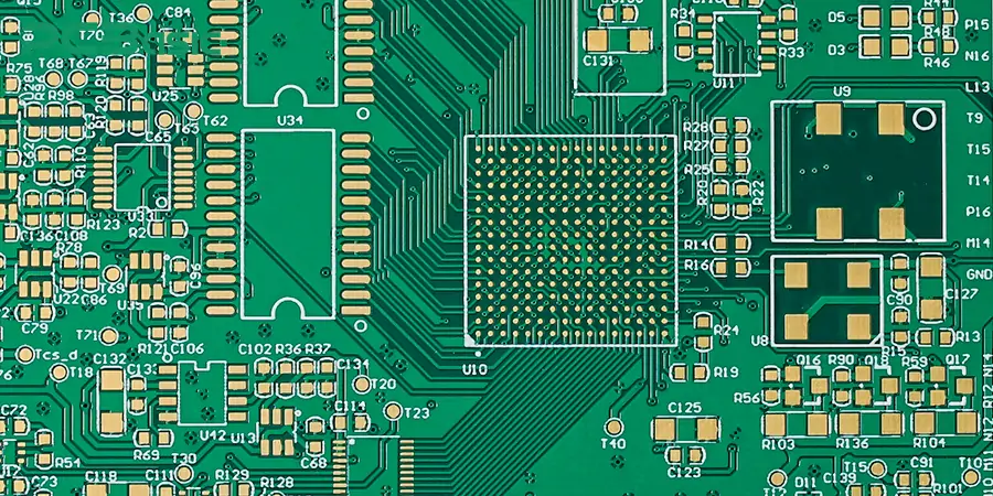
Circuit board wiring refers to the electrical connection between electronic components on a printed circuit board (PCB) through structures such as traces, vias and pads. In other words, wiring a circuit board is to design the transmission channels for signals and power on the circuit board. The various electronic components are connected through copper traces, vias and pads to build a complete electronic circuit. Among them, we often use the "copper trace width calculator" in the design, to determine the width of the wire to ensure that it can safely carry the current and meet the thermal management requirements.
The process of circuit board wiring is the core link in circuit board design, determining the performance, reliability and manufacturing efficiency of the product. Whether it is a simple circuit board or a complex circuit board wiring, such as keyboard circuit board wiring or earphone circuit board wiring, reasonable wiring is the key to determining the performance, anti-interference ability and manufacturability of the circuit.
The circuit board wiring determines:
1. Whether the transmission path of the signal is smooth;
2. Whether there are problems such as crosstalk, electromagnetic interference (EMI), and signal reflection;
3. Whether the current can flow safely and whether it will cause the traces to overheat or even damage the components;
4. Whether the electronic board assembly goes smoothly
For example, the wiring of the headphone circuit board should minimize noise interference as much as possible. The wiring of the furnace control circuit board must ensure stability and power drive capability at high temperatures. The circuit board wiring diagram can provide intuitive and clear circuit references for the entire development, debugging, production and maintenance.
Good wiring not only helps to enhance the reliability of the PCB structure, but also makes it easier to be identified in AOI and functional tests, thereby reducing the defect rate and improving manufacturing efficiency.
Since wiring is the core of PCB connectivity and performance, the table below highlights how it differs from related processes like soldering, routing, and assembly:
|
Item |
Wiring |
Soldering |
Routing |
Assembly |
|
Definition |
Conductive paths connecting parts |
Joining components to PCB with solder |
Planning signal paths on a PCB |
Mounting components to complete a circuit |
|
Stage |
Design / Physical implementation |
Manufacturing process |
PCB design stage |
Final stage of PCB manufacturing |
|
Tools/Materials |
Copper traces, wires, conductive paste |
Solder, flux, soldering tools |
PCB design software (e.g., Altium) |
Pick-and-place machines, soldering equipment |
|
Purpose |
Establish electrical connections |
Ensure electrical and mechanical bonding |
Improve signal integrity and layout |
Enable full circuit function in end products |
There are also many types of circuit board wiring. During the process of circuit board wiring, it is crucial to understand different wiring structures and conductive materials.
Common types of circuit board wiring include:
1. Single-sided Wiring: All the wiring is located on one side of the PCB. Single-sided wiring is suitable for low-cost and low-density designs, such as LED light boards and control boards for small household appliances. Its advantages are simple manufacturing and low cost. However, the wiring space is limited and the functions are also restricted.
2. Double-sided Wiring: The lines are distributed on both the upper and lower sides of the PCB and are connected through vias. This type of wiring is suitable for applications of medium complexity, such as "earphone circuit board wiring" or the main control board of household devices. Double-sided wiring can balance cost and wiring space and is widely used in industrial and consumer electronic products.
3. Multilayer Wiring: Using copper layer structures with 4 layers, 6 layers, or even more layers. Multilayer wiring is suitable for handling scenarios with complex logic and a large number of signals and power supplies separated, such as keyboard circuit board wiring, wireless communication modules, and highly reliable furnace control systems. This wiring method can achieve advanced design goals such as high-speed signal wiring, impedance control, and EMC optimization. It is often used in combination with high-frequency routing techniques: in conjunction with PCB routing techniques to achieve better signal paths and more compact board layouts.
The most commonly used conductor material for wiring is copper. Because copper has extremely strong electrical conductivity and high reliability. There are also rare aluminum and silver/gold coatings (aluminum is often used in combination with the insulating layer for wiring on metal substrates (such as MCPCB), and it is used in situations with high heat dissipation requirements; Silver/gold coatings will be used in high-frequency or anti-oxidation requirements.) There are still some materials closely related to wiring. For instance, the base material copper foil coating (FR4+ copper foil, where FR4 is a common substrate material and copper foil is attached to it to form the basis for wiring), conductive adhesives (used to replace solder connection wiring in flexible circuit boards or special applications), and surface materials such as HASL and ENIG for protecting the wiring.
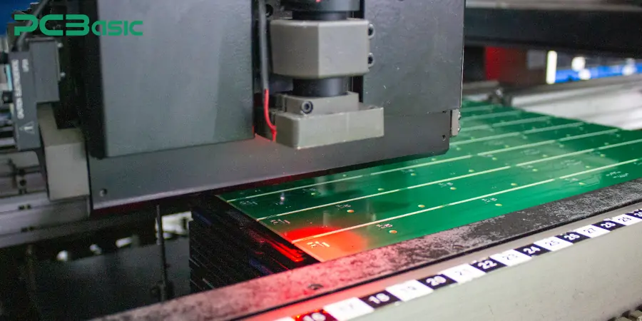
In the entire circuit board manufacturing process, circuit board wiring is not only the basis of signal transmission, but also directly affects the subsequent circuit board assembly process. Especially the efficiency and yield of SMT and DIP processes.

During the SMT process, unreasonable routing may lead to difficulties in identifying the mounting equipment and increase the occurrence rate of problems such as missing chips, misalignment, and material throwing. For instance, if the wiring around the solder pad is too dense, it will affect the quality of solder paste printing and reflow soldering. During the DIP insertion stage, the wiring should avoid the component pin area to prevent vias and wires from blocking the insertion pins, thus avoiding soldering defects.
A high-quality wiring strategy can also significantly enhance production efficiency. For instance, if the wiring direction is designed in accordance with the flow direction of the production line, it will not only facilitate machine identification and positioning but also reduce the time for manual intervention. The copper trace width calculator can be used to set the line width reasonably according to the actual current size, avoiding problems such as overheating of the conductor and voltage drop, and improving the reliability of the entire board.
In addition, the wiring design also needs to take into account the detection stage, especially the layout requirements for automatic optical inspection (AOI) and online testing (ICT/FCT). When making the circuit board wiring diagram, sufficient space should be reserved for the test points to avoid the wiring blocking the solder joints, thereby improving the recognition rate and detection efficiency. The high-density printed circuit board should uniformly plan the test points in a fixed area to enable the probes to make rapid contact and improve the test efficiency and accuracy.
To sum up, reasonable PCB routing techniques not only improve signal integrity, but also are the core elements for achieving high-efficiency assembly of electronic parts and high-yield electronic board assembly.
Reasonable PCB wiring techniques can enhance signal integrity and reduce noise interference. The following are some wiring tips:
1. Manual wiring and automatic wiring. Manual wiring is suitable for handling circuits sensitive to electromagnetic interference, such as furnace control circuit board wiring, keyboard circuit board wiring or earphone circuit board wiring, etc. Manually adjusted routing paths help optimize the return path and signal isolation. Automatic wiring, on the other hand, is applicable to simple circuit boards with regular structures or high-speed digital boards. Automatic wiring is the automatic generation of layout through EDA tools, which can accelerate the design efficiency of printed wiring boards or printed circuit boards.
2. Digital signals and analog signals should be wired separately. Separate the wiring of digital and analog signals can avoid crosstalk and interference, and enhance the overall stability of the circuit board.

3. High-frequency signals adopt impedance control for wiring. For RF or high-speed circuits, it is recommended to use methods such as microstrips or striplines to achieve impedance control. This is helpful for improving the signal quality.
4. Avoid right-angle turns and reduce the number of vias to minimize signal reflection and enhance signal integrity and reliability.
5. Adding a thermal relief structure can improve the welding quality and is particularly suitable for areas with high power or large current.
6. Optimize the width and spacing of the wiring. Use the copper trace width calculator to calculate the wiring width reasonably to ensure the conductivity, avoid overheating, and improve safety and manufacturability.
7. Every decision made in the PCB trace design stage will affect the subsequent assembly PCB process, so the routing design and assembly need to be considered collaboratively. For example, unreasonable wiring can interfere with the assembly of electronic parts, resulting in rework or a decrease in yield.
8. During the design stage, creating a clear circuit board wiring diagram can help understand the PCB structure and also facilitate debugging and maintenance during the board assembly stage.
|
Issue |
Description |
Solution |
|
Crosstalk |
Interference between adjacent signal traces causing signal distortion or false triggering |
Increase spacing, add ground shielding, use differential pairs |
|
Ground Loops |
Multiple grounding points cause circulating currents, leading to noise or oscillation |
Use single-point grounding or large ground planes |
|
Incomplete Nets |
Unconnected signal lines may result in open circuits or malfunction |
Perform DRC checks (Design Rule Check) to verify net integrity after routing |
|
Trace Overheating & Loss |
Insufficient trace width causes high resistance, heat buildup, or even burnout |
Increase trace width or use parallel traces to reduce resistance and power loss |
Circuit board wiring is far more than just "drawing lines on a PCB"; it is the foundation for determining whether a circuit board can operate stably, reliably and efficiently throughout its entire life cycle. Good PCB routing design can effectively avoid common problems such as crosstalk, grounding loops and overheating of conductors. It is beneficial to signal integrity, thermal management and electromagnetic interference control, and at the same time can improve assembly efficiency and manufacturing yield. Whether wiring a simple circuit board or a complex multilayer printed wiring board, understanding the impact of wiring on electrical performance and physical assembly is the key to achieving high-quality delivery.
 About PCBasic
Time is money in your projects – and PCBasic gets it. PCBasic is a PCB assembly company that delivers fast, flawless results every time. Our comprehensive PCB assembly services include expert engineering support at every step, ensuring top quality in every board. As a leading PCB assembly manufacturer, we provide a one-stop solution that streamlines your supply chain. Partner with our advanced PCB prototype factory for quick turnarounds and superior results you can trust.

Assembly Enquiry
Instant Quote
Phone contact

+86-755-27218592
In addition, we've prepared a Help Center. We recommend checking it before reaching out, as your question and its answer may already be clearly explained there.
Wechat Support

In addition, we've prepared a Help Center. We recommend checking it before reaching out, as your question and its answer may already be clearly explained there.
WhatsApp Support

In addition, we've prepared a Help Center. We recommend checking it before reaching out, as your question and its answer may already be clearly explained there.
