Introduction
Circuit boards are an essential component of most electronic products, and these boards have multiple components soldered on them. Hence, if they stop working or go through a failure, the most important concern is looking for the right circuit board repair solution.
This guide below comprises some easy and quick tips to help you with circuit board repair. You will learn many details about how you can efficiently address circuit board failures and, hence, will be able to repair printed circuit boards whenever you encounter a failure.
Table of Contents:
● Why Do You Need to Know Circuit Board Repairing
● Why Do Circuit Boards Repair
● Common PCB Failures
● What Materials are Necessary for Circuit Board Repair
● How to Repair a Circuit Board
● The Issue of Fixing A Circuit Board by Yourself
● Safe Tips on PCB Board Repair
● FAQs About Circuit Board Repair
Why Do You Need to Know Circuit Board Repairing?
Repairing circuit boards could be a hobby of someone, and it could also be a solution to fix circuit boards in case of encountering a failure. Once you have mastered repairing printed circuit boards, you can maintain systems professionally.
These days, most electronic products comprise PCBs, and knowing about their functioning and repairs is essential. Electrical engineers' skills make them competent to repair circuit boards.
However, if you also learn about circuit board repairs, you can promptly diagnose and repair failures. One of the most significant advantages of learning to fix circuit boards is that it restores the working of the electronic product quickly without incurring any expense.
Irrespective of the fact, a person who is a professional or an ordinary man who likes to learn the skills of circuit board repair will gain a lot of confidence when it comes to repairing electronic products.
Why Do Circuit Boards Fail
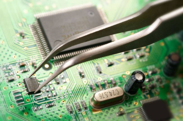
Circuit board repairing becomes easier, provided that you know the reason for its failure; once you identify the root cause, you can come up with a solution. Many reasons lead to failure in circuit boards, and they need repairs. Some of the reasons for these failures are as follows:
Damaged Components
In most circumstances, the failure of a printed circuit board is associated with the physical damage on the part of the components it has present on it. These physical damages may be due to pressure or shock. Sometimes, the device faces a crash after falling from a height, so the circuit board gets damaged.
Defects in Assembling the PCB
PCB is sometimes not assembled properly, which also leads to failure. There is a problem in assembling the components on the board, or the components have defects. These components may comprise diodes, ICs, transistors, or a microprocessor. In such cases, the damaged ones need replacement or repair.
Damaged Traces on the Circuit Board
The circuit boards have traces, which are paths made out of silver and copper. If these traces get damaged, the board may not function. The most common reasons for this kind of damage are overheating or contamination due to dust; sometimes, power surges also cause damage to the path.
Poorly Designed Circuit Board
The design of the PCB may need improvement; each stage of assembling the circuit board involves many people, and the designs may require revision at some points. The installation of components may have flaws, or the electronic components may leak from the welding.
Impact of Environmental Factors
Extreme temperatures impact the PCB boards negatively, and environments with excessive humidity and heat cause damage to PCBs. These PCBs may get exposed to water, air, and some chemicals that cause their components to rust. In this case, the chances of short circuits increase, so PCB board repair may be necessary.
Damage due to Static Electricity
The PCB assembly process is associated with specific defects, leading to a problem of static electricity. The static electricity damages the PCB, which requires repairs in such cases.
Damage Due to High Temperature
The assembly of certain PCBs is such that they have the components placed very close to one another. Due to the closeness of these components, the high temperature generated may lead to the burning of the electronic components, and the PCB faces failure.
Common PCB Failures
PCB Short Circuit
There are many faults caused by PCB. The short circuit is the most common problem in PCB failure. A short circuit can make the PCB not work properly.
1) The most significant cause of the PCB short circuit is improper solder pad design. At this point, the circular pad can be changed to an oval, increasing the distance between the point and point, to prevent short circuit. While we're at it, it's a good idea to change the shape of the round pad. We can make it an oval. The purpose of this is to increase the distance between the points. That way, there won't be a short circuit.
2) We know that there are a lot of electronic components on the circuit board. The directional design of these electronic components is important. If these electronic components are in the wrong direction, a short circuit is bound to occur. Let's take an example to understand that. Parallel directions of IC pins and tin waves can cause a short circuit on the circuit board. If we encounter this situation, carefully check the orientation of the PCB electronics. IC foot perpendicular to the tin wave is the safest design.
3) Now let's discuss the third cause of PCB short circuits. We all know that automatic plug-ins can cause short circuits. That's the crooked foot. We must ensure that the pins do not exceed 2mm. If the pin is too long, the electronics will fall off. Electronic components that fall off the PCB can cause a short circuit. So when we weld electronic components, we make sure that the distance between the solder joint and the circuit is less than 2 mm.
In addition to the three common reasons we mentioned, some reasons can cause a PCB short circuit. For example, the substrate hole is too large; the temperature of the tin furnace is too low; the solderability of the board is poor; the solder mask is invalid, and the board Surface pollution, etc. Engineers can compare the above reasons for eliminating and inspecting the PCB board.
PCB Open
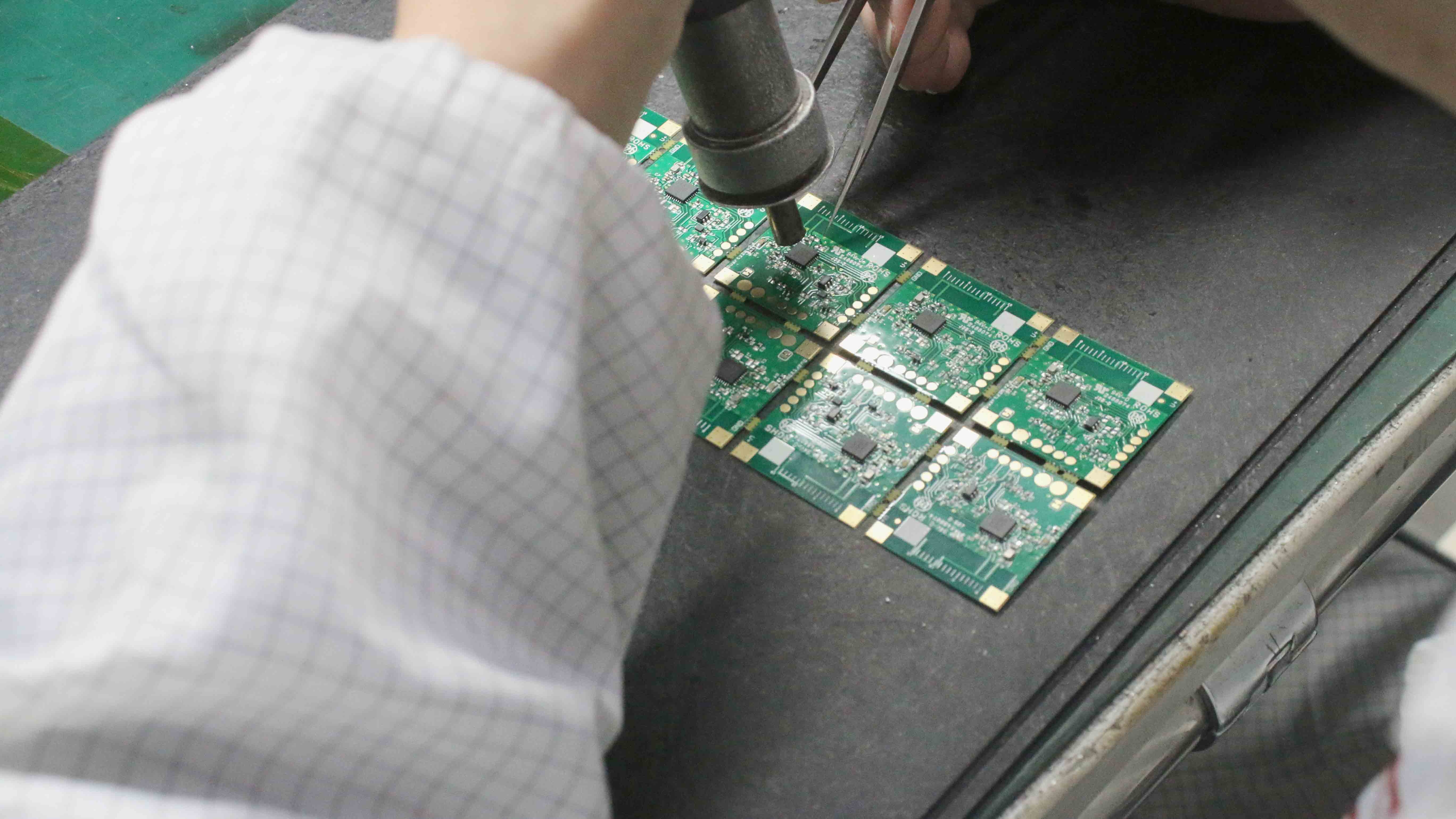
When the trace is broken or the solder is only on the pad and not on the component lead, the PCB will open. In this case, there is no adhesion or connection between the component and the PCB. Like short circuits, these may also occur during the production process or the welding process and other operations. Vibration or stretching of the circuit board, drop, or other mechanical deformation factors will destroy the traces or solder joints of the PCB board. Similarly, chemicals or moisture can cause solder or metal parts to wear, which can cause component leads to break.
Dark and Grainy Contacts Appear on the PCB Board
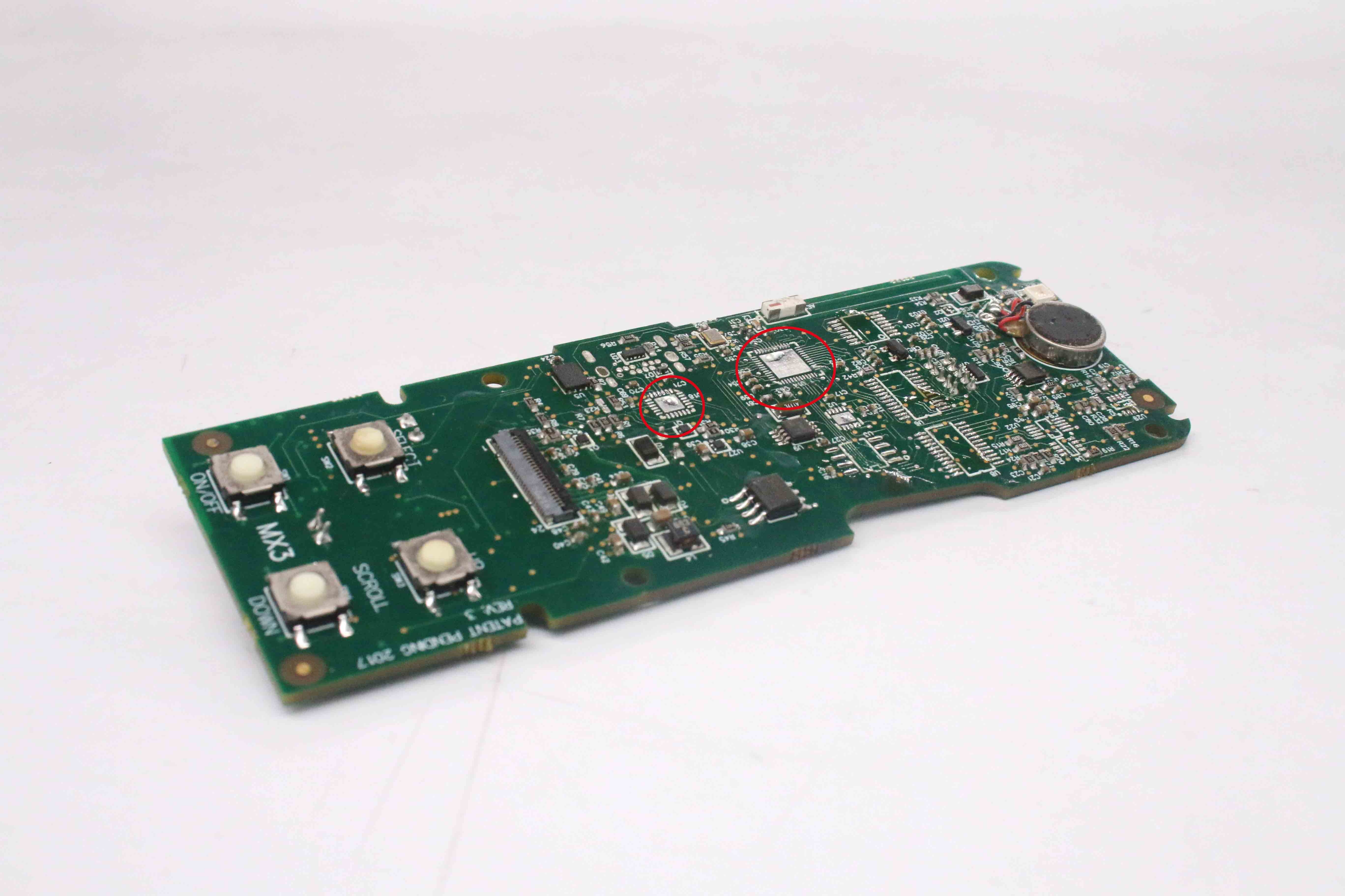
Contact problems on PCB boards are mainly due to: the solder being contaminated, and the oxides mixed in the molten tin are too much; the resulting solder joint structure is too brittle. Be careful not to use solder with low tin content. Otherwise, it will easily cause dark color confusion.
Another reason for this problem is the change in the composition of the solder used in the PCBA manufacturing process. The most typical is that the solder contains too many impurities, and pure tin needs to be added or replaced. As a result, the stained glass causes physical changes in the fiber buildup, such as separation between layers. But this situation is not due to poor solder joints. The reason is that the substrate is heated too high, so it is necessary to reduce the preheating and soldering temperature or increase the speed of the substrate.
PCB Solder Joints Turn Golden Yellow
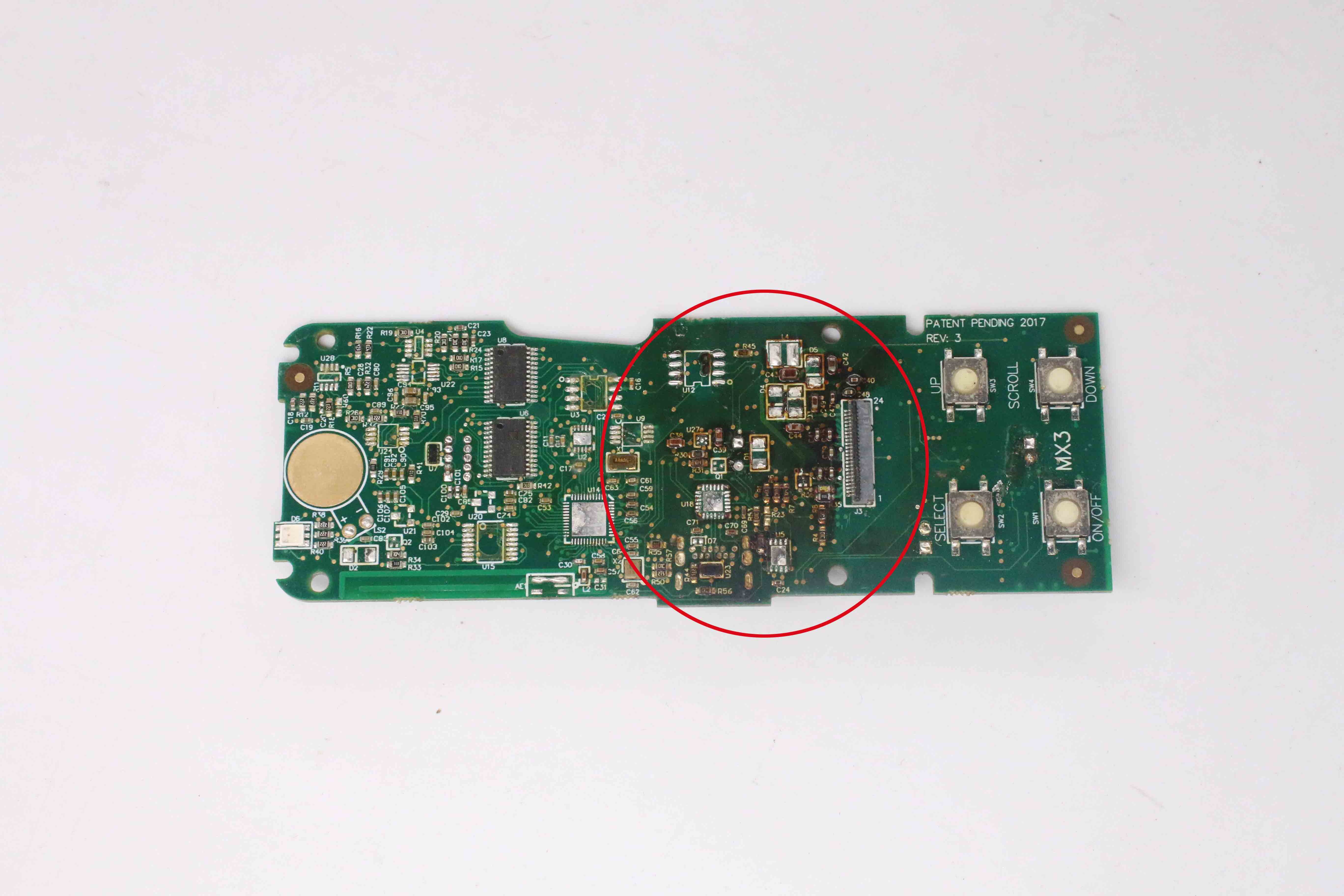
Under normal circumstances, the solder on the PCB board is silver-gray. Occasionally, golden solder joints appear. The main cause of this problem is the high temperature. At this time, it is necessary to lower the temperature of the tin furnace.
Bad Boards are Also Affected by the Environment
Due to the PCB structure itself, it is easy to cause damage to the PCB when it is in an unfavorable environment. Extreme temperature or temperature fluctuations; excessive humidity; high-intensity vibration, and other conditions are all factors that cause the performance of the board to be reduced or even scrapped. For example, changes in ambient temperature will cause deformation of the board. Therefore, this situation will destroy the solder joints; bend the board's shape, or cause the copper traces on the board to open.
On the other hand, moisture in the air can cause oxidation of the metal surface; corrosion, and rust; such as exposed copper traces, solder joints, pads, and component leads. Dirt buildup on the surface of components and circuit boards; dust or debris will also reduce the airflow and cooling of the components; causing PCB overheating and performance degradation. Vibration, dropping, hitting, or bending the PCB will deform it and cause cracks. The high current or overvoltage will cause the PCB board to be broken down; or drive the rapid aging of components and paths.
What Materials are Necessary for Circuit Board Repair?
Most printed circuit board repairs require the same or improved materials used in the official design.
If you are searching for "electronic board repair near me," please contact us. Our PCB repair services can help you reassemble or repair the damaged circuit board to make it close to its original state. There is almost no difference between the previous version and the upgraded version. Of course, this requires many skills and experience, which you will not find outside the experienced professional environment of circuit board repair.
An essential part of professional PCB repair services is to ensure that they have the suitable PCB repairing materials and tools to complete the work. Some PCB board repair teams did not provide everything on the property or on-site, and they must wait to receive the necessary materials or tools. This may increase the time required for circuit board repair or reassembly of parts.
It is no secret that many materials used in circuit board repair are not environmentally friendly or not conducive to safety. We still have a long way to go, but scientists and cutting-edge teams are studying biodegradable PCBs, which decompose naturally after being discarded.
How to Repair a Circuit Board
Electronic circuit board repair is most commonly after thermal and physical damage and excessive voltage to the components. So, how to repair a circuit board step by step? Here is the guide:
1. Collect Necessary Tools for Circuit Board Repair
First, collect all the essential tools you need to repair a printed circuit board. These crucial tools include:
● Sharp knife or flathead screwdriver or fantastic sandpaper
● Sticky copper tape
● Welding gun
● Hot air gun
● Scissors or craft knife
● Pen
● Cotton swabs and rubbing alcohol
● Tweezers
● Paper clip
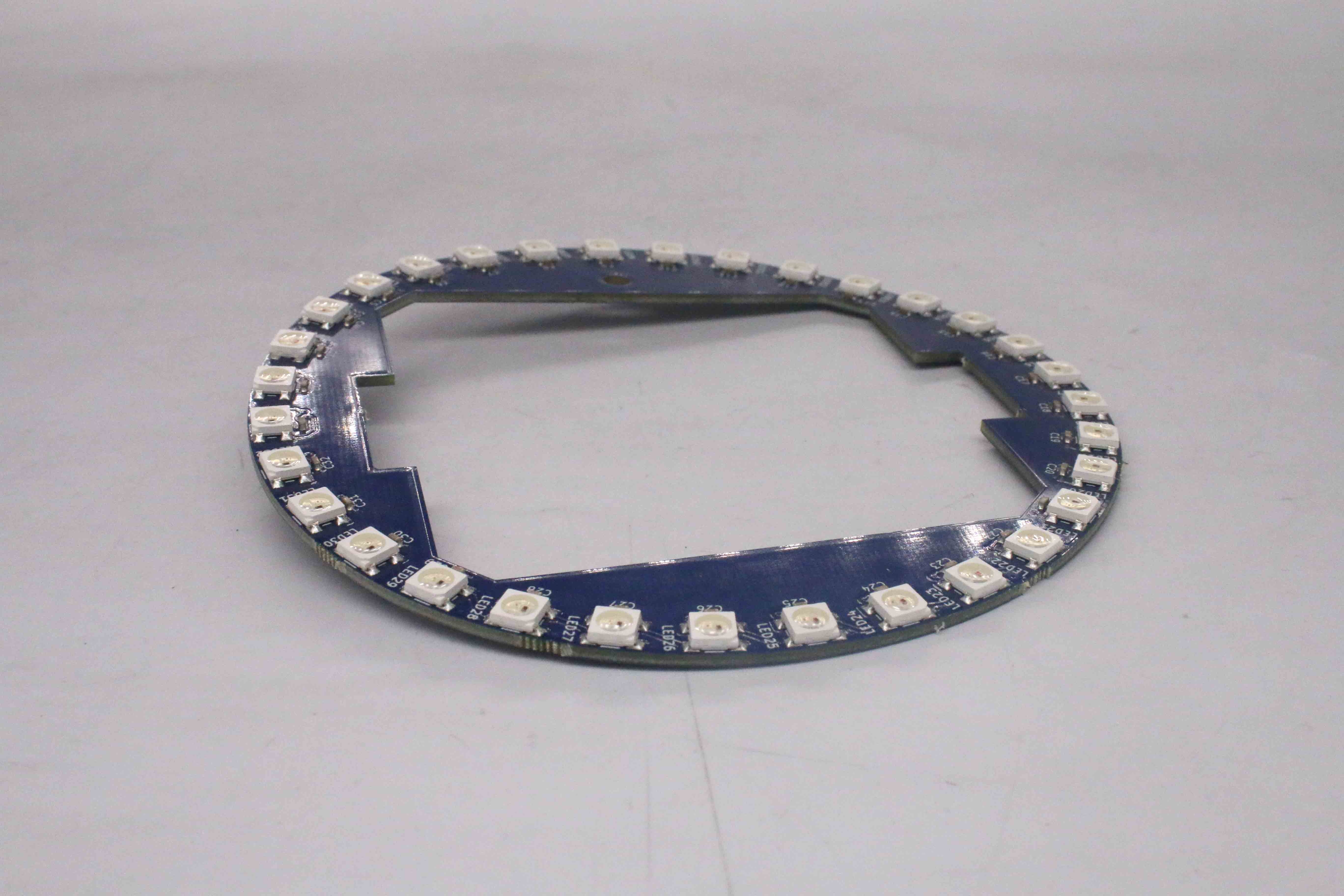
2. Remove Damaged Component
To repair circuit boards, you need to start with the removal of damaged components first. Before this, fix the PCB board to your work surface to avoid it moving around while working. Then, you can use your knife or a screwdriver with a flathead to remove the damaged part from the board. You can remove the solder with sandpaper if the circuit board pad is damaged.
3. Clean the Track and Remove Solder
After repairing solder pads on a circuit board, use a sharp knife to remove the existing solder. If you are not used to using a knife on this relatively delicate part of the operation, you can also use a pointed screwdriver or fine sandpaper. No matter which tool you prefer, the result should be a wholly exposed track, with no existing solder, looking bright and clean. By doing this, you will be sure the new component is accurately installed.
To clean the placement location more efficiently, dip a piece of cotton in rubbing alcohol and wipe off any residue present. Also, remove the damaged areas of the track using scissors and mark the end of the track to place your new component.
4. Place the Copper Tape on the Track
After removing the damaged track and cleaning up the area, it is time to put your sticky copper tape on top of the site you are using. Your tape should overlap the existing track and cover part of the current through the hold and surrounding area.
5. Weld the Joints
It is necessary to carefully solder the joints between the new copper tape and the existing track on the repaired PCB board. Place the tip of the soldering gun, which is already heated, on the copper tape and keep holding it until a strong bond forms and the solder has cooled down.
Here are some tips and warnings about this part of the process: The copper strip will melt rapidly at the soldering temperature, so don't start until you're sure you can complete this part of the process in one go. Use as little heat as possible and work deliberately but quickly to reduce the heat applied.
6. Restore PCB Vias
Find a hard tool with a round tip, such as a pen or other simple device. Press down the area just soldered and rubbed it hard to ensure that the copper tape is firmly attached to the entire pad area. After heating the area, the adhesive should still be sticky. Using this technique, you will determine the hole's location, which you can then pierce with a paperclip or other similar tool.
7. Place and Solder Your Components
After the track repair, the next step is soldering the new component. You must insert the component's lead in the PCB through-hole. Once the lead has passed in the hole, you have to apply some amount of solder with the help of a solder gun and hold it until it sets.
The process should be familiar. However, as before, you need to shorten the healing time as much as possible. The new joint you formed between the newly pasted copper tape/pad and the track may be somewhat fragile.
8. Remove Excessive Tape
Once the new component is placed in its location, you can remove the excessive tape in the repaired area. Using scissors or a craft knife, carefully cut the sticky copper tape to the appropriate size to complete the circuit board repair. It is important to note that the connector you just repaired may restore functionality to your PCB. But the pads, tracks, and connectors will never be structurally as intact as the original board. Nonetheless, you have taken many things that others would throw aways as trash and give it a new life.
9. Test the Board
Once you finish the printed circuit board repair, you should test it. To test the PCB and its functions, it is essential to assess its voltage and current, and for this, you can use a multimeter.
Also, placing the board back in the device lets you see if it is operating properly. If any problem persists, troubleshoot and check the solder joints, traces, and components in case further repair is needed.
The Issue of Fixing a Circuit Board by Yourself
You can easily repair a circuit board on your own, but when doing this, you may also sometimes compromise the board's reliability. The heating and cooling cycle of the board disrupts every event, and hence, the life of the board is reduced.
It is imperative to assess the life of the board after circuit board repair takes place.
Safety Tips on PCB Board Repair
When you are looking forward to fixing a circuit board, some safety precautions are essential to take:
Wearing Safety Glasses
Printed circuit board repair comprises the soldering stage; some solder circuit board repair causes the melting of wire, and sometimes the fluid may get splashed. In such circumstances, wearing safety glasses is imperative to protect the eyes.
Unplug the Equipment
Before you start circuit board repair, unplug the equipment and ensure the PCB board is not charged. It is essential for the power supply and the capacitor to be disconnected because leaving them plugged could lead to electrocution.
Opt for an Anti-static Wrist Strap
Safety is a significant concern when carrying out electronic circuit repair. Hence, in case of computer board repair or any other kind of board repair, you will need to maintain precautions to avoid the generation of static electricity.
It is suggested to wear an anti-static wrist strap when repairing the PCB board to avoid this static electricity passing into you and keep yourself safe.
Ensure Cleanliness
When starting the circuit board repair, you must have your hands clean and ensure that the PCB's edges are clean so that your maintenance process continues with no issues. If you start repairing with dirty or wet hands, there is a chance of a short circuit. Hence, sanitize your hands before you start working with the board.
Designate a Clean Workspace
Ensure that the area where you will carry out circuit board repair is clean and has sufficient light. That workspace needs to be free from all kinds of static electricity sources.
Static electricity can damage critical components on the board, and to prevent this, you can use gloves, an anti-static wrist strap, or an anti-static mat to work over. Your workspace should be away from all kinds of liquids and heat sources.
FAQs About Circuit Board Repair
1). How Much Does PCB Repair Cost?
On average, the circuit board repair costs around $50 to $150; however, this may vary depending on the damaged component. Sometimes, the component needs repair, and sometimes, it needs replacement. The price fluctuates accordingly.
2). Can a Burnt Circuit Board be Repaired?
A burnt circuit is a cause of overheated PCB, and in such cases, the layer of copper on the PCB de-laminates from the board made of fiberglass. It leads to damaged and broken circuits, some of which are repaired using copper tape.
3). How Do You Find the Bad Components of a Circuit Board?
To find out the bad component on the circuit board, you will first need to turn off the power and unplug the device from electricity. Afterward, use a multimeter to test each component, which will help you determine which parts are not working.
4). What Causes a Circuit Board to Go Out?
PCB board repair may be required for many reasons. The most common failures include aging of components, wear and tear, loss of current, reduced resistance and capacitance, etc. These failures occur due to environmental factors like weather and moisture.
5). How Can You Tell If a Circuit Board is Blown?
To determine if the circuit board has blown, you must scrutinize it and look for cracked points, broken wires, and any marks of burn and bulges on the board.
6). What Causes a Circuit Board to Fry?
Usually, three reasons lead to PCB fry:
● Extreme heat
● Lack of spacing between components
● Any failure on the part of the components
7). How Do I Find a Circuit Board Repair Service Near Me?
You can search for a circuit board repair near you online or by word of mouth. You must review the reviews of the customers shared on the repair service website to ensure that you choose the right repair service.
8). Should I Be Worried About Static Electricity While Repairing a PCB?
Static electricity is generated in the PCB, and while repairing it, you must consider wearing anti-static clothes and an anti-static wristband.
9). How Do I Reduce Thermal Stress on Components While Reworking a Circuit Board?
Thermal stress is one of the main causes of damaged PCB, and you can reduce it by installing a heat sink on the PCB as it helps with the hot and cool cycles of the circuit.
10). How Do I Remove Conformal Coating for PCB Repair?
You can remove the conformal coating from the PCB while repairing it using acetone or rubbing alcohol.
Conclusion
After going through the detailed guide above, you must know how to repair a circuit board or where to get a circuit board repaired. By exercising caution and following every step carefully, you can quickly fix circuit boards professionally following the earlier steps. If you have any comments or questions, please let us know.
Looking for a PCB or PCBA quote? Contact us now.


