Global high-mix volume high-speed PCBA manufacturer
9:00 -18:00, Mon. - Fri. (GMT+8)
9:00 -12:00, Sat. (GMT+8)
(Except Chinese public holidays)
Global high-mix volume high-speed PCBA manufacturer
9:00 -18:00, Mon. - Fri. (GMT+8)
9:00 -12:00, Sat. (GMT+8)
(Except Chinese public holidays)
HomePage > Blog > Knowledge Base > How Do Circuit Boards Work?
You are sure to find printed circuit boards in almost all electronic devices. That ranges from radios, televisions, smartphones, LED lights, and computers.
In any electronic equipment, a circuit board helps receive or send signals. But how do circuit boards work? What are the roles of various PCB components like transistors, diodes, resistors, and capacitors?
The guide provides detailed information that helps answer questions like how PCBs work and what a circuit board is.
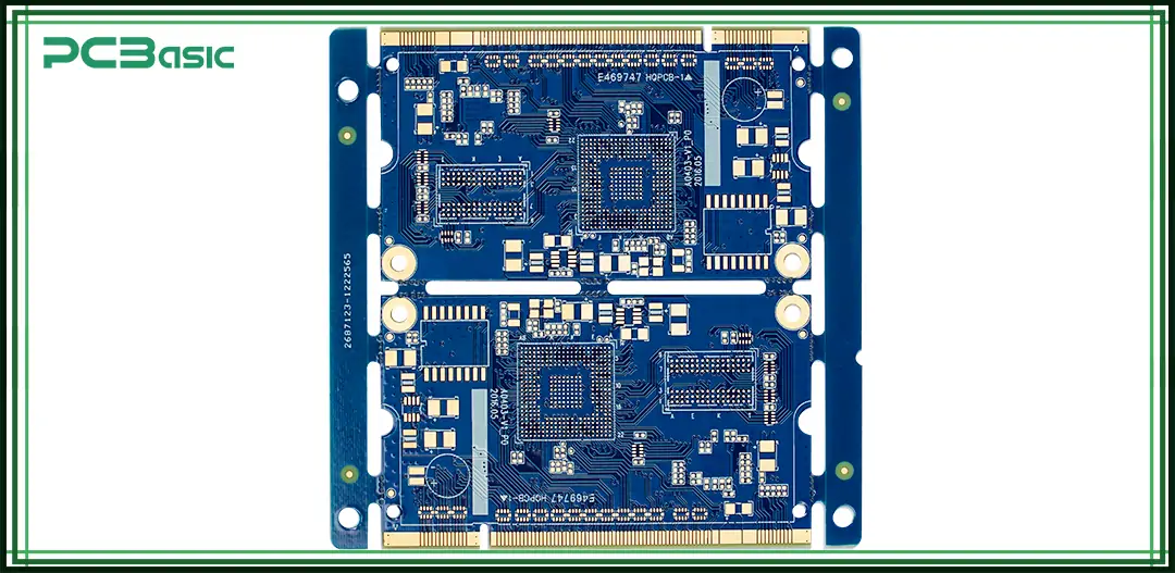
A circuit board is a flat, non-conductive piece of material that holds different electronic components joined by interconnective paths called traces. The circuit board can be of single, double, or multilayers.
Before printed circuit boards (PCBs) were invented, early electronic devices used point-to-point wiring. This method connected each electronic component with wires by hand. It was complex, took up a lot of space, and often caused errors like wrong connections, short circuits, or bad solder joints. Maintenance was also difficult.
In the 1930s, Austrian engineer Paul Eisler created the first modern circuit board. He used a process to etch copper onto an insulating base. This replaced manual wiring and made circuits easier to produce. His invention improved both the reliability and efficiency of electronic products.
Over the following decades, circuit board design kept improving. At first, components were still soldered by hand. Later, engineers used software to create PCB layouts, and machines were used for automated production. Today, circuit boards support multilayer structures and high-density interconnect (HDI) designs. These advances allow electronic devices to become smaller, lighter, and smarter.
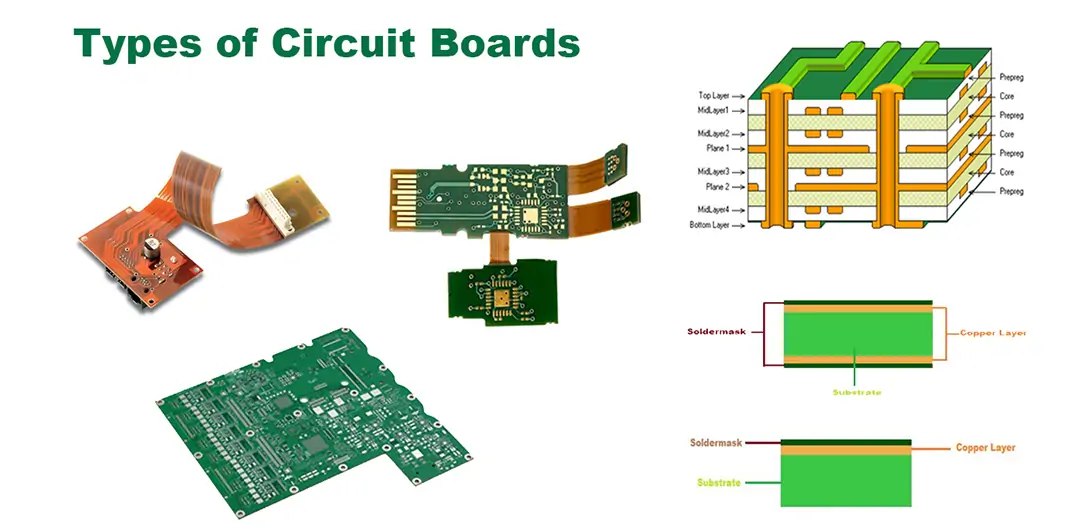
A single-layer PCB is also termed a single-sided circuit board. The type of circuit board is easy to come across and attracts an affordable cost. Further, a single-sided PCB has a conductive copper layer on one side, and the opposite side features a layout for the electronics components.
Although single-sided circuit boards are cheap to produce, they suffer some limitations. Consequently, it isn't the preferred option for high-end applications.
Double-sided circuit boards are also termed as double-layer PCBs. Just like their single-sided counterpart, double-sided features have a single substrate. However, the core material features a thin layer of conductive material on either side of the board.
Also, double-sided circuit boards tap on the surface mount and through-hole technologies. Doing so enables the circuits on either side to connect via the plated through holes. What such a circuit board does is that it allows for the mounting of components on both surfaces.
The introduction of double-layer technology has enabled circuit boards to handle more complex applications than before.
Unlike single- or double-layer PCBs, multilayer circuit boards employ multiple substrate materials. In other words, it's a circuit board that combines three or more double-sided PCBs into one unit.
Thus, in real life, you can find PCBs of four, six, eight, twelve, or even more layers on the boards. In multiple-layer circuit boards, electronic components are only on the top and bottom layers. All other stacked units help in routing.
A multiple-layer circuit board contains high component density and numerous circuits in a smaller space. Therefore, multilayer circuit boards find applications in computers, GPS, satellites, and aerospace systems.
Note that multilayer circuit boards are demanding to design, expensive to manufacture, and challenging to repair.
Flex circuits, as the name implies, are flexible and thus foldable. The flexible PCBs can have single, dual, or multiple layers. The distinguishing feature is their flexibility. Flexible printed circuit boards employ a supple substrate material such as thin plastic, polyimide, or Kapton.
The outstanding advantage of flexible printed circuit boards is their easy handling and tolerance of extreme temperatures. Being flexible, the PCBs can assume the shape of different electronic devices.
Unlike a flex circuit, a rigid power board isn't flexible. The rigid printed circuit board uses a non-flexible substrate material. So, once you design and manufacture the board, you can not alter its shape.
Rigid circuit boards excel in strength and durability. A computer's motherboard is a typical example of a rigid PCB. Note that the power board can take any number of layers.
Rigid-flex printed circuit boards are a blend of flexible and rigid boards. By blending the two types of boards, rigid-flex PCBs are flexible yet still durable.
The high-frequency printed circuit boards find application in circuits requiring fast data processing and high frequency. Sometimes, such circuits handle data at speeds of up to two gigahertz. Such power boards are present in networking devices, radios, microwaves, and mobile phones.
The aluminum-backed PCBs use thick aluminum metal as the core material. However, the aluminum substrate has a dielectric topping and thick conductive copper layers.
Owing to their design, aluminum-backed circuit boards are sturdy, give good heat dissipation, and handle large currents. Some of their typical applications are in LED lighting, the automotive industry, and power supplies.
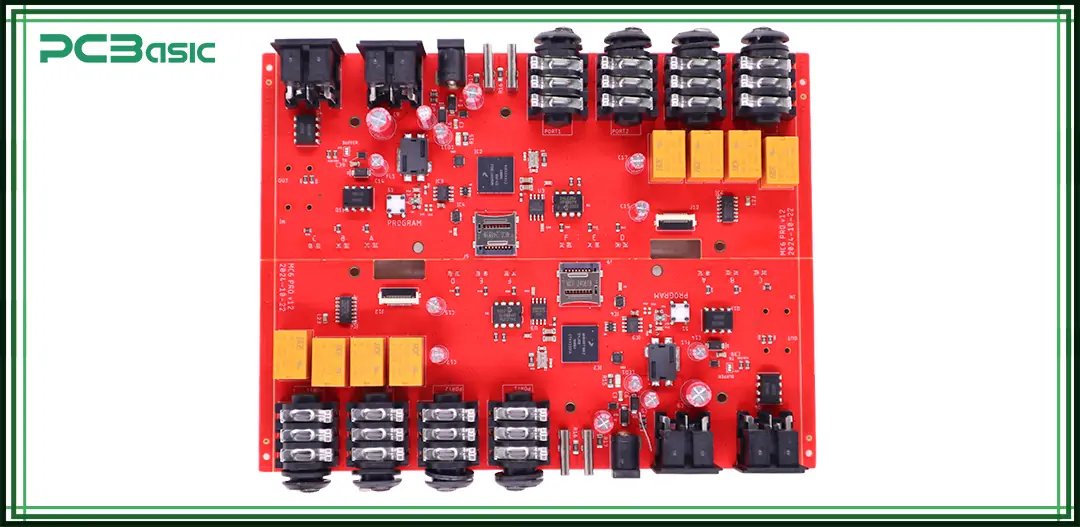
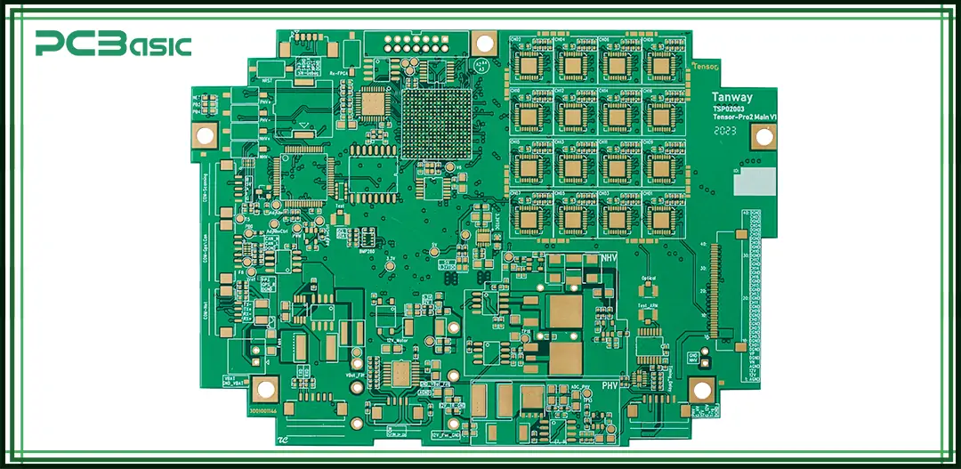
The main function of a circuit board (PCB) is to transmit and distribute electrical signals between different electronic components. It creates electrical connections through copper traces on the board surface, allowing each component to operate as designed.
These copper traces are usually created by an etching process and are placed on an insulating substrate. They act like pathways, guiding electrical current from the power source to the required components—such as chips, resistors, capacitors, diodes, or connectors.
The working process can be divided into the following steps:
• Power Input: Electrical current first enters the electronic board from an external power supply.
• Signal Transmission: The current flows through copper traces to different parts of the circuit board and to specific component locations.
• Function Execution: Each component performs its intended task, such as controlling voltage, current, logic operations, or signal processing.
• Output: The processed signals are sent to the output devices, such as a display, motor, or speaker.
Throughout this process, the PCB ensures accurate and stable signal flow. This method of signal routing is the foundation of proper operation in all electronic devices.
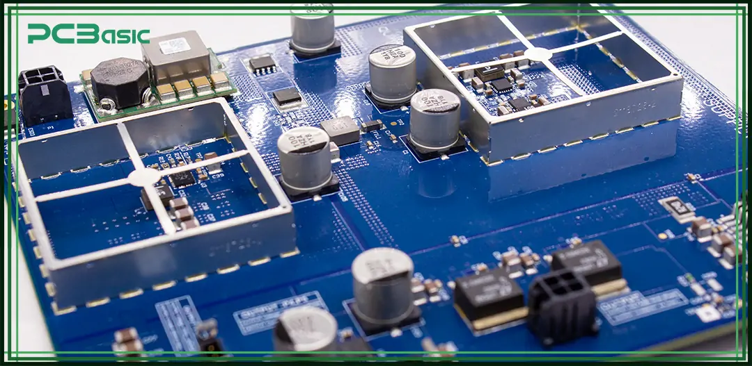
To understand how a circuit board works, it's important to first learn about its physical structure. A standard printed circuit board (PCB) is made up of multiple layers. Each layer has a specific function and plays a key role in signal transmission and electrical performance.
Here are the main structural layers of a circuit board:
• Substrate: This is the base layer of the PCB. It is usually made from FR4 fiberglass material. The substrate provides mechanical support, structural strength, and electrical insulation for the entire board.
• Copper Layer: This is a conductive layer placed directly on top of the substrate. It is usually made of copper. Through an etching process, the copper is shaped into traces that connect different circuit board components and carry electrical signals and power.
• Solder Mask: This is a protective layer applied over the copper traces. It is usually green. The solder mask prevents short circuits during soldering and protects the copper from oxidation and physical damage.
• Silkscreen: Printed on top of the solder mask, this layer includes text and symbols. It helps identify component locations, reference numbers, and orientation, making assembly, testing, and repair easier.
• Vias and Pads: Vias are small holes that go through the board and connect copper layers across different levels. Pads are flat surfaces where component leads are soldered. They ensure secure and reliable mounting of electronic components.
Each of these layers plays an important role in how the PCB works. Choosing the right materials and using a well-designed layer stack-up helps ensure stable signal flow and improves the reliability of the entire electronic system.
You can only understand how a PCB works after knowing its constituents. Each mechanical and electrical device on a circuit board plays a distinct role. They include the following:
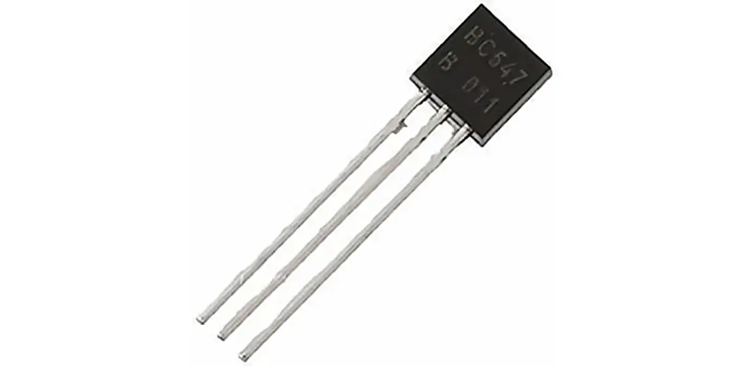
A transistor is a semiconductor device that plays a vital part in a circuit board. It helps to amplify electronic signals or plays the role of a signal-controlled switch.
The amplified signal then travels through the trace and switches on another high-power semiconductor device. Transistors on a circuit board are either PNP or NPN type.

Another vital component of a circuit board is a resistor. Resistors play the role of regulating the amount of current flowing through a device.
When current flows through a resistor, the device dissipates heat and thus regulates the current. They are of two types: fixed and variable. On a printed circuit board, resistors have the symbol of the letter R.
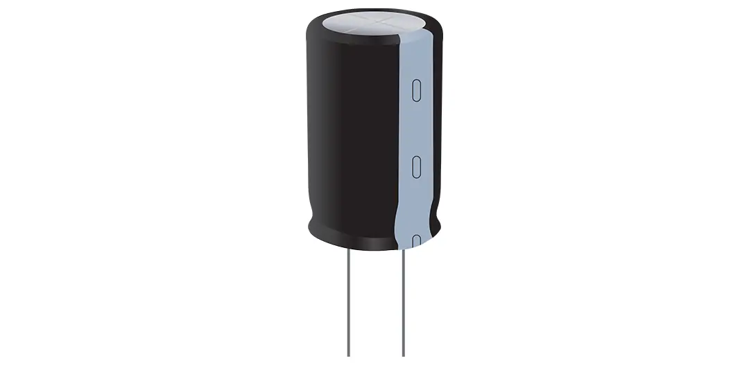
The symbol for a capacitor is the letter C. Capacitors store charges in an electrostatic field for a momentary period. It then releases an outburst of power at the appropriate time through discharge. One widespread use of capacitors is smoothening the ripples of a rectified AC power.
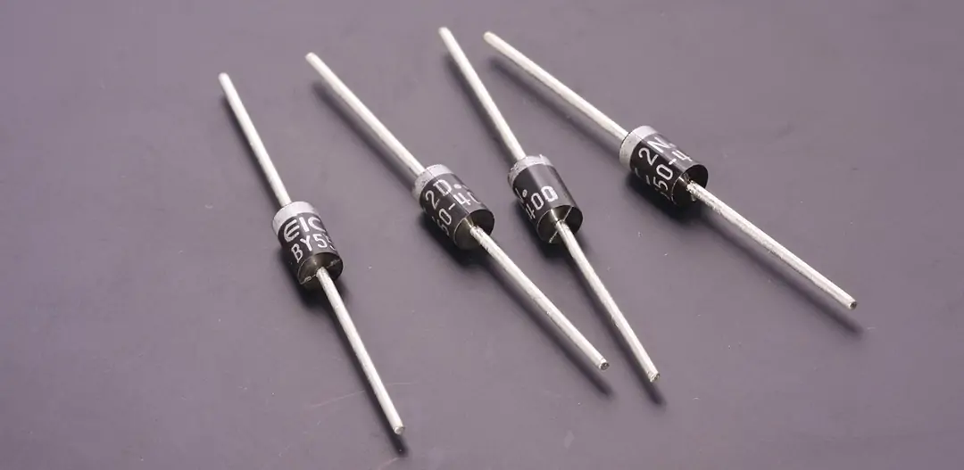
Diodes are semiconductor devices that conduct current in one direction only. They differ in size and amount of current they can safely carry without breaking down.
The unidirectional property of the diode makes it ideal for rectifying alternating current, AC into direct current, DC. One famous type of diode is the light-emitting diode, LED. As the name suggests, LED glows when an electric current passes through it.
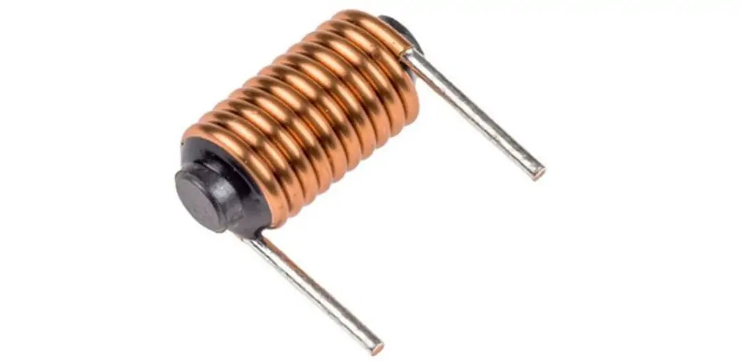
An inductor is yet another common component of a circuit board. An inductor stores energy from an electric current in a magnetic field. In most cases, inductors are used together with capacitors to form an LC circuit.
Transformers have electromagnetic properties. The role of a transformer is to moderate the energy transfer from one part of the board to the next. While doing so, it isolates one part of the circuit board and protects sensitive devices. A transformer can either step up or down power in a circuit as required.
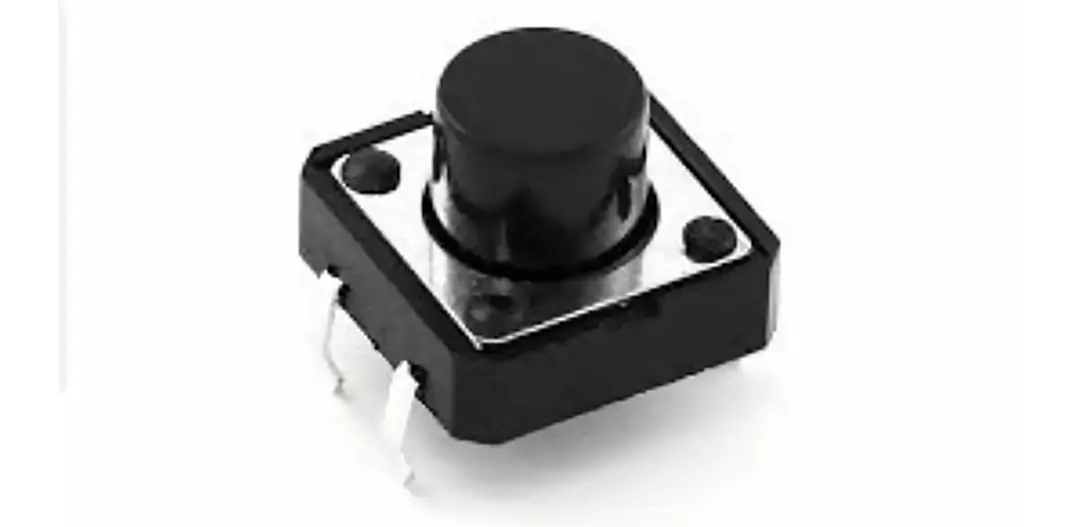
A switch in the on position allows current to flow. However, when the switch is open, it cuts off the current through a board.
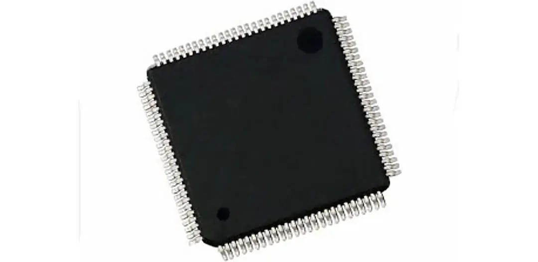
An integrated circuit is commonly known as an IC. As the name implies, an IC contains numerous circuits involving miniaturized components integrated into it. Another name for ICs is microchips, and they play multiple roles in a circuit board.
Printed circuit board (PCB) manufacturing is a precise and complex process. Its goal is to turn a digital PCB layout designed by engineers into a real, working electronic board. The process includes several key steps. Each step affects the final performance and reliability of the product.
Below are the main steps of PCB manufacturing, explained in order:
1. Design and Layout
Engineers use CAD (Computer-Aided Design) software to create the circuit board design. This includes drawing the circuit schematic, placing components, planning traces, and defining layer structure. The final output is the Gerber files, which are used in manufacturing.
2. Image Transfer
The PCB design is printed onto a copper-clad laminate (the base material). This is done using exposure and development processes. This step defines the basic shape and location of the copper traces.
3. Etching
Unwanted copper is removed from the board. Only the necessary conductive traces remain. These traces form the actual electrical paths between components. This step ensures the PCB layout is accurately formed.
4. Drilling and Plating
CNC machines drill holes into the PCB for component leads and vias. Then, the holes are plated with copper. This allows electrical connections between different copper layers.
5. Solder Mask and Silkscreen
A solder mask layer is applied to cover the traces. It is usually green and protects the copper from oxidation and short circuits. After that, a silkscreen layer is added to show part numbers, component positions, and orientation. This helps with assembly and inspection.
6. Component Assembly (PCBA)
Electronic components are mounted on the board according to the design. This can use SMT (Surface Mount Technology) or THT (Through-Hole Technology), depending on the component type and product requirements.
7. Testing and Inspection
The assembled board is tested with electrical, functional, and visual inspections. This checks for open circuits, short circuits, soldering problems, and if all key components work properly. These steps ensure that the PCB works correctly and meets quality standards.
Q1: How do circuit boards work in simple terms?
They use copper pathways to carry electrical signals between components, enabling devices to perform tasks.
Q2: What are the main parts of a circuit board?
Substrate, a copper layer, solder mask, silkscreen, and various circuit board components like resistors, ICs, and capacitors.
Q3: How does a circuit board get designed?
Using CAD tools, engineers create a PCB layout based on function, component placement, and routing needs.
Q4: How do PCBs work in harsh environments?
By using durable materials, conformal coatings, and proper circuit board design, PCBs can withstand heat, vibration, and moisture.
Q5: What’s the difference between a PCB and an electronic board?
They’re essentially the same—“electronic board” is a general term, while “PCB” specifically refers to the physical platform.
Q6: Do circuit boards use AC or DC?
Most circuit boards, if not all, use DC (direct current) instead of AC (alternating current). In most cases, a battery or rectified AC provides the direct current the board requires. A rectifier unit that changes AC to DC consists of a transformer, rectifier diodes, and a filter circuit.
Q7: What powers a circuit board?
A circuit board receives its power from a battery or PCB power supply. A PCB power supply takes power from the wall socket and changes it to a DC level that the board needs.
Q8: What is inside a circuit board?
A single-sided circuit board has a single layer of conductive copper material on one side and another side for mounting electronic components on the same board.
Q9: Why are circuit boards usually green?
Most circuit boards are usually green since they use the green protective solder mask. So the entire board isn't green through, only the outer part. The mask protects the traces from moisture and dust and prevents solder messes.
In the olden times, circuit board inspection was mainly by eye inspection. And green color reduces eye fatigue.
Modern electronic devices have circuit boards of varying sizes. But the principle of what a circuit board does is the same. Whether it's a single, dual, or multilayer board, it relies on various electronic components to accomplish its function.

Assembly Enquiry
Instant Quote
Phone contact

+86-755-27218592
In addition, we've prepared a Help Center. We recommend checking it before reaching out, as your question and its answer may already be clearly explained there.
Wechat Support

In addition, we've prepared a Help Center. We recommend checking it before reaching out, as your question and its answer may already be clearly explained there.
WhatsApp Support

In addition, we've prepared a Help Center. We recommend checking it before reaching out, as your question and its answer may already be clearly explained there.
