Global high-mix volume high-speed PCBA manufacturer
9:00 -18:00, Mon. - Fri. (GMT+8)
9:00 -12:00, Sat. (GMT+8)
(Except Chinese public holidays)
Global high-mix volume high-speed PCBA manufacturer
9:00 -18:00, Mon. - Fri. (GMT+8)
9:00 -12:00, Sat. (GMT+8)
(Except Chinese public holidays)
HomePage > Blog > Knowledge Base > Flex Printed Circuit Board | FPCB
Flexible Printed Circuit Board, known as FPCB, emerged as a game changer in modern electronics with its ability to flex, bend, and fit in complex geometries. FPCBs are widely used in industries due to their various advantages, including flexible structure, lightweight, compact, and ability to fit in various spaces.
Flexible PCBs are generally made from polyimide or polyester film material. These materials’ properties allow FPCBs to flex and bend without being damaged. Their ability to flex and bend makes them a popular choice for many electronic manufacturing industries where compactness and robustness are required, including wearable electronics, handheld electronic devices, medical devices, and consumer electronics.
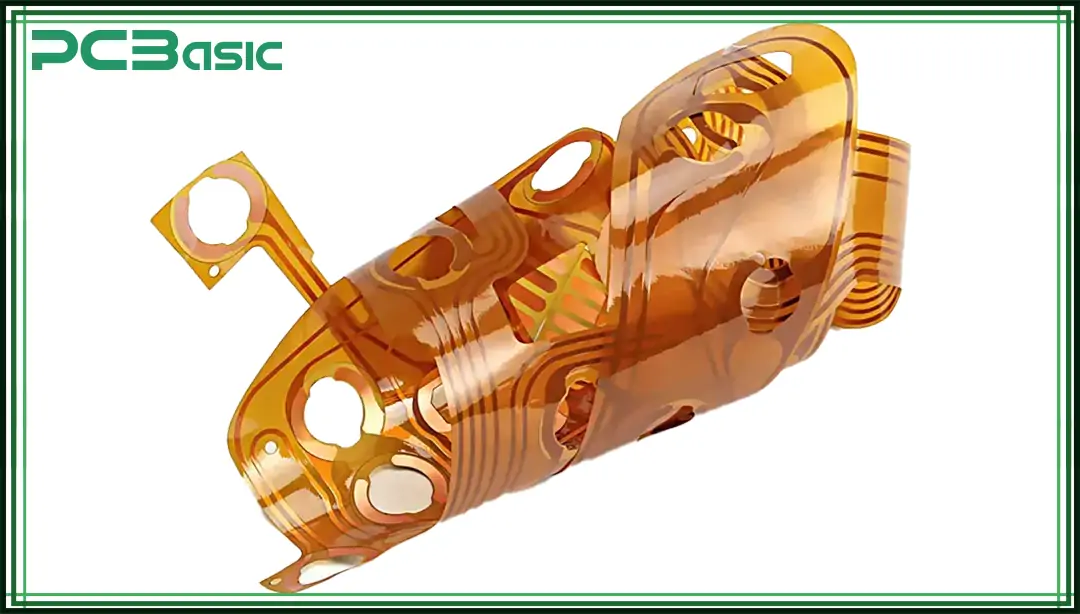
The FPCB structure plays a vital role in determining the functionalities of the printed circuit board. The basic elements of the FPCB structure are as follows;
· Conductive Layer: The conductive layer of FPCB is made up of copper, providing the necessary electrical conductivity for the circuit.
· Dielectric Substrate Layer: The dielectric substrate serves as a physical base in FPCB layer structures for conductive materials.
· Adhesive Layer: The adhesive layer in FPCBs is used to bind the substrate to copper foil, resulting in board height and flexibility.
· Coverlay: Coverlay is made of polyimide material and protects the conductive circuits from dust and moisture.
· Stiffeners: Stiffeners are mostly FR4 material, which is used to strengthen areas and make the FPCB more robust.
Rigid PCBs and Flexible PCBs consist of multiple layers laminated together. FPCB layers differ a bit from traditional PCB layers due to their flexibility. The FPCBs can be categorized based on their layers.
1. Single-Sided FPCB: Single-sided Flex PCB is considered the simplest board that consists of a substrate layer, conductive layer, overlay, and silkscreen only. It is called single-sided FPCB because it has only a single layer of flexible polyimide or polymer film. Therefore, the conductive copper layer is reachable on one side of FPCB. The other side of this type of PCB is used to place electronic components.
· Why Single-Sided FPCB? Among all types of FPCB, the single-sided flexible PCB is widely used in many electronics applications including wearable and consumer electronics due to their simplicity, and cost-effectiveness.
2. Double-Sided FPCB: In double-sided flexible PCB, trace patterns can be created on either side of the PCB. The accessibility of both top and bottom side copper layers makes it a suitable choice for dense electronic boards. In double-sided flexible circuit board layers can be connected using the through holes.
· Why Double-Sided FPCB? These boards have the flexibility to use both sides to create trace patterns and therefore, are suitable for complex and dense electronic products such as medical devices, and consumer electronics. They are suitable when more functionality is required within a limited area.
3. Multilayer FPCB: Multilayer flex PCB, as the name suggests, has multiple copper layers that are connected using the through holes. Multilayer flex PCBs are complex among all types because they consist of individual copper and dielectric layers. Mostly multilayer flexible circuit boards are suitable choices for applications where design freedom, dense design requirements, and multiple functionalities are required in a limited area such as smartphones, space electronic devices, digital cameras, and heart pacemakers.
· Why Multilayer FPCB? Multilayer FPCBs are mainly suitable for complex designs where various functionalities are desired in limited areas such as hearing aids and heart pacemakers.
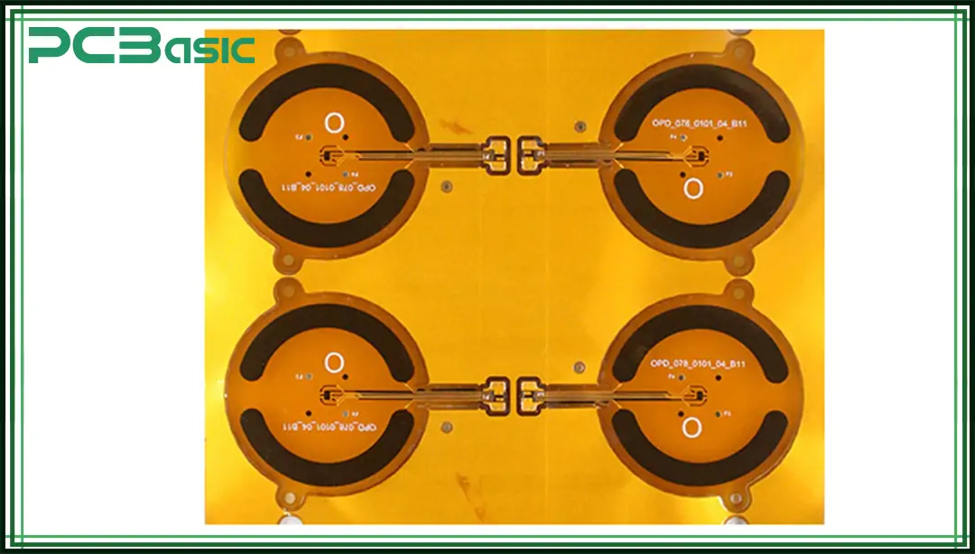
Flexibility in FPCBs is achieved using specialized materials. Basic materials that are used in flex circuit boards are substrate material, conductive material, and adhesive materials.
The base material used for almost all types of PCBs is the same which is woven fiberglass. Although these materials are used in rigid printed circuit boards, it is not the fiberglass that makes them rigid but the curved epoxy that makes the board rigid. The single laminated layer has enough flexibility that it can be used for simple flexible circuit boards where constant movement is not required. The commonly used material choice for flexible PCBs is flexible polyimide and heat resistant. Polyester can also be a choice for flexible PCBs, but it is not often used or preferred because it cannot survive in high temperatures of soldering.
The most typical conductor material used for cheap electronics is copper. Copper comes in different forms and it depends on the application that which copper is suitable. For example, if you aim to reduce the time and manufacturing cost by eliminating the cabling and connectors then the copper foil is a fine choice. If your application requirement is continuous bending and flexing of the circuit board, then copper foil is not the best choice, and you may consider high-grade foils. The high-grade foil improves the FPCB flexibility, but it increases the cost considerably. So, it is a trade-off between achieving high-grade flexibility and cost saving. The annealed foil improves the flexibility that is required for flexible PCBs.
Simply speaking, adhesive is a material that is used to bond the two materials together to form a strong bond. In flexible PCBs or rigid PCBs, adhesives are required for bonding the copper foil. In FR4 material, annealed copper has fewer teeth, and heat is not enough to make a robust bond. Thus, adhesives play a critical role in making a strong bond and providing the flexibility required for FPCBs.
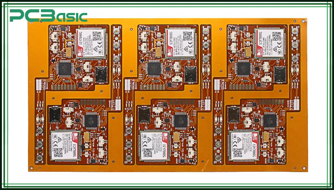
Based on the configuration, FPCB is typically classified into static and dynamic flexible PCBs.
Static flexible PCBs are designed for applications where minimum movement is required. Usually, they are designed to bend in a specific radius. In the assembly process, static flex PCBs are bent beyond radius curvature and angle using a specialized tool to ensure plastic deformation during forming. When you are defining the bending radius and angle it is important to consider margin of safety in track thickness. This is important to ensure that the hairline should remain intact and not crack.
Dynamic flexible PCBs are used where more freedom of flexibility is required such as in robotic arms. Whether it is static or dynamic PCBs, the design considerations for flex PCBs are usually the same except for the fact that dynamic PCBs are designed for more repeated bending and folding. The durability of these flexible PCBs is increased to achieve a greater bending and curvature angle.
The typical steps involved in the manufacturing process of FPCBs include:
1. Material Selection: This step is critical in the manufacturing process of FPCBs as it determines the overall flexibility of the circuit board. Usually, the polyimide material is used as a substrate due to its heat resistance and durability. Copper layers are used to create trace patterns. This step is critical in the manufacturing process of FPCBs as it determines the overall flexibility of the circuit board. Usually, the polyimide material is used as a substrate due to its heat resistance and durability. Copper layers are used to create trace patterns.
2. Circuit Pattern: Photo resistive material is applied to the surface of copper and it is exposed to UV light via mask to create a desired circuit pattern. Using the etching process the undesired copper is removed.
3. Drilling and Through Hole Process: Holes are created using a specialized device for vias and through holes. Through holes and vias are made conductive using copper to connect them with other layers of flexible PCB.
4. Component Placement: First, solder paste is applied using a stencil. Using a pick and place machine components are placed on the designated pad of components.
5. Reflow Soldering: The FPCB is now passed through a reflow oven to heat the solder paste. Upon heating the solder paste, it melts and creates a strong connection between components and pads.
6. Inspection & Testing: Using specialized equipment, FPCBs are inspected to identify any errors. Automated Optical Inspection Machine scans the FPCB and detects any missing components and solder bridges. X-ray inspection is also done to identify any soldering defects in the FPCB.
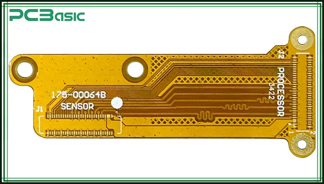
FPCBs ability to flex and fold makes it ideal for many industry applications, including satellites, consumer electronics, wearable electronics, and medical devices.
Medical Devices: Flexible PCBs are compact, lightweight, and reliable, and their ability to fit in complex geometries makes them ideal for many medical devices such as Pacemakers, hearing aids, CT scans, MRI machines, and diagnostic equipment.
Consumer Electronics: Modern consumer electronics are becoming smart with each passing day and it demand for lightweight, compact, and efficient PCBs. FPCB fills this gap and is used in many applications including Smartphones, Smartwatches, laptops, and wearables.
Automotive Industry: Automotive industry is transforming with modern technologies. Modern vehicles require seamless communication between sensors. FPCBs are becoming popular in the automotive industry and are used in dashboard displays, sensors, and vehicle lighting systems.
Industrial Automation: The world is shifting towards automation, and robots are becoming popular in many applications. FPCBs provide the required flexibility and reliability to robotic arms to make them efficient and autonomous.
Flexible PCBs have their unique advantages. However, they offer some disadvantages but it depends on the requirements and type of application for which you are designing FPCB.
|
Pros of FPCB |
Cons of FPCB |
|
FPCBs are flexible as they can be bent and folded. They can easily be fitted into complex geometries. |
FPCBs' manufacturing cost is higher than that of traditional FPCBs. |
|
FPCBs are lightweight and compact, making them suitable for applications where space and weight are integral. |
The FPCB assembly process is complex. |
|
FPCBs offer fewer connection joints and eliminate the need for connectors. This improves the signal integrity. |
FPCBs are not designed to carry large currents and thus carry only limited currents. |
|
FPCBs are durable as compared to traditional PCBs due to their ability to bend up to 360 degrees. Their durability enables them to survive extreme vibrations and mechanical stress. |
FPCB repair and reworks are difficult. |
|
FPCBs are good at heat dissipation due to their thinner substrate. |
Testing and troubleshooting of FPCBs is difficult as compared to rigid PCBs. |
1. Based on your application, choose the right substrate material for your FPCB design.
2. Make an accurate bend radius to avoid any failure.
3. Always use staggered Vias in FPCB design.
4. It is not recommended to use solder joints. Therefore, always try to use minimum solder joints.
5. Optimize trace width to reduce resistance.
6. Always perform comprehensive testing for FPCBs before integrating them into the design.
7. Always use proper heat dissipation techniques in FPCB design.
8. Use proper shielding techniques to minimize EMI interference.
9. Appropriately use overlay materials to ensure durability.
10. Use proper techniques to prevent cracks in Flex PCB.
|
Feature |
Rigid PCB |
Flexible PCB |
|
Structure |
These PCBs are rigid and cannot bend and fold. |
FPCBs are designed to bend and fold. |
|
Weight |
Rigid PCBs are Heavy |
FPCBs are lightweight and compact. |
|
Cost |
Rigid PCBs have a low manufacturing cost |
FPCBs have high manufacturing costs. |
|
Durability |
These PCBs are more susceptible to failure upon mechanical stress. |
FPCBs are designed to withstand mechanical and vibration stress. |
|
Assembly |
These are easy to assemble |
They are difficult to assemble. |
|
Applications |
Suitable for applications such as desktop computers, servers, and industrial applications. |
Suitable for smart and compact applications such as smartphones, smartwatches, and other consumer electronics |
Flexible PCBs emerged as a game changer in modern electronics by offering flexible, reliable, lightweight, and space-saving solutions for various applications including wearable electronics, consumer electronics, and medical industries. FPCBs' ability to fit into complex geometries makes them ideal for modern electronic designs. FPCBs manufacturing cost is higher but their advantages outweigh their disadvantages.

Assembly Enquiry
Instant Quote
Phone contact

+86-755-27218592
In addition, we've prepared a Help Center. We recommend checking it before reaching out, as your question and its answer may already be clearly explained there.
Wechat Support

In addition, we've prepared a Help Center. We recommend checking it before reaching out, as your question and its answer may already be clearly explained there.
WhatsApp Support

In addition, we've prepared a Help Center. We recommend checking it before reaching out, as your question and its answer may already be clearly explained there.
