Logic gates are the building blocks in digital electronics that perform mathematical operations, comparisons, and decision making. It has been shown that XOR and XNOR gates are very crucial because they actually detect the difference and equality between two inputs.
In it, we will cover in detail:
· What XNOR and XOR gates are
· Their symbols, truth tables, and Boolean logic.
· They are different and they are alike.
· Real-world applications.
· Examples of how they function in circuits.
What is XNOR?
XNOR, or Exclusive NOR, is a composite logic gate combining the logic of XOR and NOT. It returns true (1) if both inputs are the same, otherwise displays false (0).
A ⊙ B = ¬(A ⊕ B)
Where:
· ⊕ denotes XOR
· ‾ denotes NOT
· ⊙ is commonly used to denote XNOR
This translates to: "An XNOR B is the not of A XOR B.''
Let’s expand further:
A ⊕ B = A'B + AB'
Therefore:
A ⊙ B = AB + A'B' = ¬(A ⊕ B)
That is, the output of XNOR is 1 when both inputs are 00 or 11.
Real-world Analogy
Think of a vault with two keys. The vault opens (output is 1) when both keys are either inserted (1,1) or both are missing (0,0). This is the condition that XNOR tests for.
XNOR Gate
An XNOR gate is a digital logic gate that performs logical equality. It therefore only has a high output (1) when both inputs are equal (1) (2).
Characteristics:
· Binary inputs: 0 or 1
· Output: 1 - if inputs are equal, else 0
· Also called: Equivalence gate
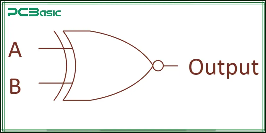
XNOR Symbol
Now, notice that the XNOR is the inversion of the XOR gate, which means we add an inversion circle (bubble) at the output that indicates NOT.
· The curved shape denotes XOR
· The small circle (bubble) indicates the NOT operation
· Combined, it becomes XNOR = NOT XOR.
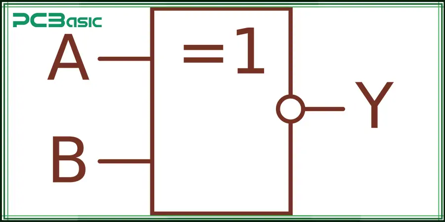
IEEE Symbol:
Depending on the notation, the IEEE standard may show the same functionality, but they usually keep the inversion circle.
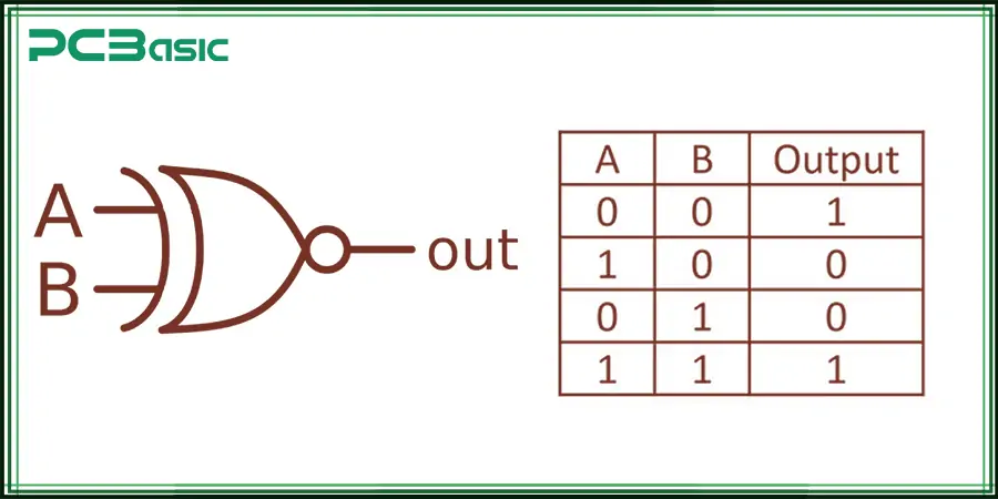
XNOR Gate Truth Table
LOOK — XNOR gate truth table showing its true inputs (1) when matching:
|
A
|
B
|
¬(A ⊕ B)
|
|
0
|
0
|
1
|
|
0
|
1
|
0
|
|
1
|
0
|
0
|
|
1
|
1
|
1
|
In both cases, similarly mapped input on the left side (0,0 or 1,1) simply means that the output is 1 — Where inputs are equal.
What is XOR?
XOR — Exclusive OR — is a logic operation that returns true if the inputs are not the same. It is “exclusive” because it does not include the case when both inputs are identical.
Boolean Logic
A⊕B=A′B+AB′
This means:
· The output is 1 if one is 1 and other is 0
· The output is 0 when both inputs are the same.
Real-world Analogy
Visualize a light that will turn on only when one of the two switches is flipped. As long as both switches are in the same position, the light remains off.
XOR Gate
This is Why the XOR gate is used to detect the inequality or differences in digital logic. It is found widely in arithmetic logic units (ALUs), error detection, and cryptography.
Characteristics
· Output: 1 if inputs differ
· Alias: Inequality gate
XOR Symbol
An XOR gate symbol looks the same as an OR gate symbol but with an additional curved line on the input side.
The key differences are:
· Input side has two curves instead of one (not like OR)
· No bubble (unlike XNOR)
XOR Truth Table
XNOR = NOT XOR (Truth table):
|
A
|
B
|
A'B + AB'
|
|
0
|
0
|
0
|
|
0
|
1
|
1
|
|
1
|
0
|
1
|
|
1
|
1
|
0
|
That means XOR is 1 if the bits are unequal.
XOR vs. XNOR
Comparing XOR and XNOR directly in Logic, Truth Table, Symbol and usage:
Logic Comparison Table:
|
Feature
|
XOR
|
XNOR
|
|
Full Form
|
Exclusive OR
|
Exclusive NOR (Not XOR)
|
|
Operation
|
True if inputs differ
|
True if inputs are equal
|
|
Boolean Exp.
|
A ⊕ B = A'B + AB'
|
A ⊙ B = AB + A'B' = ¬(A ⊕ B)
|
|
Truth Condition
|
1 when an odd number of 1s
|
1 when an even number of 1s
|
|
Common symbol
|
⊕
|
⊙ (or ⊕ with a NOT circle)
|
|
Gate Shape
|
Curved with extra line
|
XOR gate + bubble at output
|
|
IEEE Symbol
|
Standard IEEE XOR shape
|
IEEE XOR + inversion bubble
|
Truth Tables Side-by-Side:
|
A
|
B
|
XOR (A⊕B)
|
XNOR (A⊙B)
|
|
0
|
0
|
0
|
1
|
|
0
|
1
|
1
|
0
|
|
1
|
0
|
1
|
0
|
|
1
|
1
|
0
|
1
|
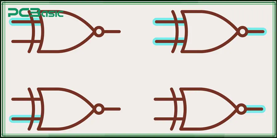
The below visual comparison illustrates how oppositional XOR and XNOR act in contrast.
XNOR and XOR Applications
So, let's begin with the concept of logic gates, which are very basic building blocks of digital electronics. The following are the key applications of XOR & XNOR gates:
XOR Gate Applications
· Half Adders and Full Adders
Half and full adders use XOR gates for binary addition. In half adders, XOR gives the sum of the two bits. In full adders, two XOR gates calculate the sum of three bits (A, B, and Carry-in), thus proving that XOR functions are a critical part of arithmetic logic in digital circuits and processors.
· Parity Bit Generators & Checker
XOR gates are used in parity bit generators and parity bit checkers. Consequently, by determining if the number of 1s in a binary sequence is either odd or even through XOR, a parity bit can be generated or checked during reception, which helps facilitate reliable data transmission and allows simple error detection methods in digital communication.
· Cryptography
Symmetric-key encryption, for example, uses XOR gates heavily in many cryptographic algorithms. Information can be encrypted/decrypted by XORing the data with a key. As such, XOR is an integral part of any cryptographic system, allowing for a relatively straightforward means of safeguarding data.
· Bitwise Operations
XOR gate are used to perform bitwise operations in programming and digital logic. The exclusive OR operator XOR, can be used to toggle bits, if the bit is XORed with 1 it gets flipped and if XORed with 0 it remains unchanged. This is critical for performing bit manipulation tasks such as masking or in data encoding.
· Toggle Mechanism
A control input uses XOR in circuits to invert a signal. The toggle functionality provides logic gates that flip signal high states that toggle from 0 to 1 or 1 to 0 which is an important fundamental circuit for many flip-flops and synchronous systems of all kinds, the flip-flop circuit, state machine, and control system.
XNOR Gate Applications
· Digital Comparators
XNOR gates play an important role in digital comparators that determine if two binary numbers are equal. The bitwise XNOR operator compares all the corresponding bits and outputs 1 when both bits are identical, and 0 when they are different. This causes systems to use it to properly accomplish equality comparisons in digital circuits
· Phase Detectors
Phase Detection Circuits: XNOR gates are used in phase-locked loops (PLLs) and other types of phase detection circuits. XNOR gates are used to compare the phase difference between two signals to detect alignment/mismatch. It is an important function of synchronization events in signal processing, frequency synthesis, and communication systems.
· Memory Check Circuits
XNOR gates are used in memory systems to verify data. XNOR gates determine whether two sets correspond by comparing data held in memory against incoming data. Such storage is only as consistent as the stored values, which is why XNOR is so important for error detection and data integrity in the realm of memory.
· Logic Equality Functions
For performing equality checking XNOR gates are used. They have two inputs and return 1 if the inputs are the same. Systems such as decision-making circuits, muxes, and others that contain input match confirmation as a precondition for system operation heavily depend on this functionality in their design throughout which data propagation is limited to anything other than what they operate on.
· Advanced Error Correction
XNOR gates are used in most error correction codes, i.e., Hamming codes. They help identify errors in the digital communication by comparing the data transmitted to the data received. In communication networks, where data needs to be reliable, XNOR gates play a significant role in maintaining data integrity and thus making them extremely important in these systems.
Multi-bit inputs, what exactly is XNOR?
To compare multi-bit inputs, multiple pairs of XNOR gates may be used to compare sets of bits at once. Such operation involves overlapping bits of two binary numbers and passing them through an XNOR gate. Each bit pair (Ai, Bi) is passed through an XNOR (⊙) gate to check equality. If both bits are the same (0 or 1), the XNOR gate returns 1; otherwise, it returns 0 (if bits differ).
Here’s an example, you want to compare two 8 bit binary numbers like:
A = 10110110
B = 10110110
Starting with your data, it might look something like this:
· A0 vs B0, A1 vs B1, A2 vs B2, A3 vs B3, A4 vs B4, A5 vs B5, A6 vs B6, A7 vs B7
· There is one XNOR gate for each pair of corresponding bits. Here, all bits are identical, and thus all of the XNOR gates will return 1, showing that the numbers match.
If any one of the bits has a different value (e.g., A = 10110110 and B = 10110011), the output of the XNOR gate for those individual bits would be 0, meaning there's a mismatch. To get the final result, the two multi-bit inputs are equal if every XNOR gate outputs a 1. Therefore, the XNOR gate is commonly used for equality checking, data validation and error detection in multi-bit systems, like in digital comparators or memory comparison circuits.
Conclusion
The XNOR symbol, along with the symbol for XOR, and how these gates operate is important for a broader understanding of digital logic, circuit design, and computational systems. Here’s a quick recap:
· XOR (⊕) detects difference, while XNOR (⊙) detects equality
· XNOR has a bubble, but otherwise their symbols are similar
· XOR in Arithmetic, and in Cryptography
· XNOR is one of the gates used in comparators and verification logic
· Truth tables are reflections of symmetry
No matter what you are doing — designing a microprocessor, building communication protocols to transmit data, implementing AI hardware, etc.. XOR and XNOR gates will certainly be at its heart.