Global high-mix volume high-speed PCBA manufacturer
9:00 -18:00, Mon. - Fri. (GMT+8)
9:00 -12:00, Sat. (GMT+8)
(Except Chinese public holidays)
Global high-mix volume high-speed PCBA manufacturer
9:00 -18:00, Mon. - Fri. (GMT+8)
9:00 -12:00, Sat. (GMT+8)
(Except Chinese public holidays)
HomePage > Blog > Knowledge Base > What is an SMT Line? SMT Assembly Line and Manufacturing Process
In the past, manufacturers had to attach electronic components onto printed circuit boards with wires through holes. It was complicated and time-consuming. And as components got smaller, a big advance was required in the electronics to automate the assembly line and increase the accuracy. Here comes SMT assembly line to rescue. It completely eliminates the need for wires and allows smaller components to be mounted to PCBs.
In this article, we’ll guide you to know what exactly an SMT line is, the key processes and equipment in an SMT production line, the layout types of SMT lines, as well as the advantages of SMT production lines over traditional PCB assembly lines.
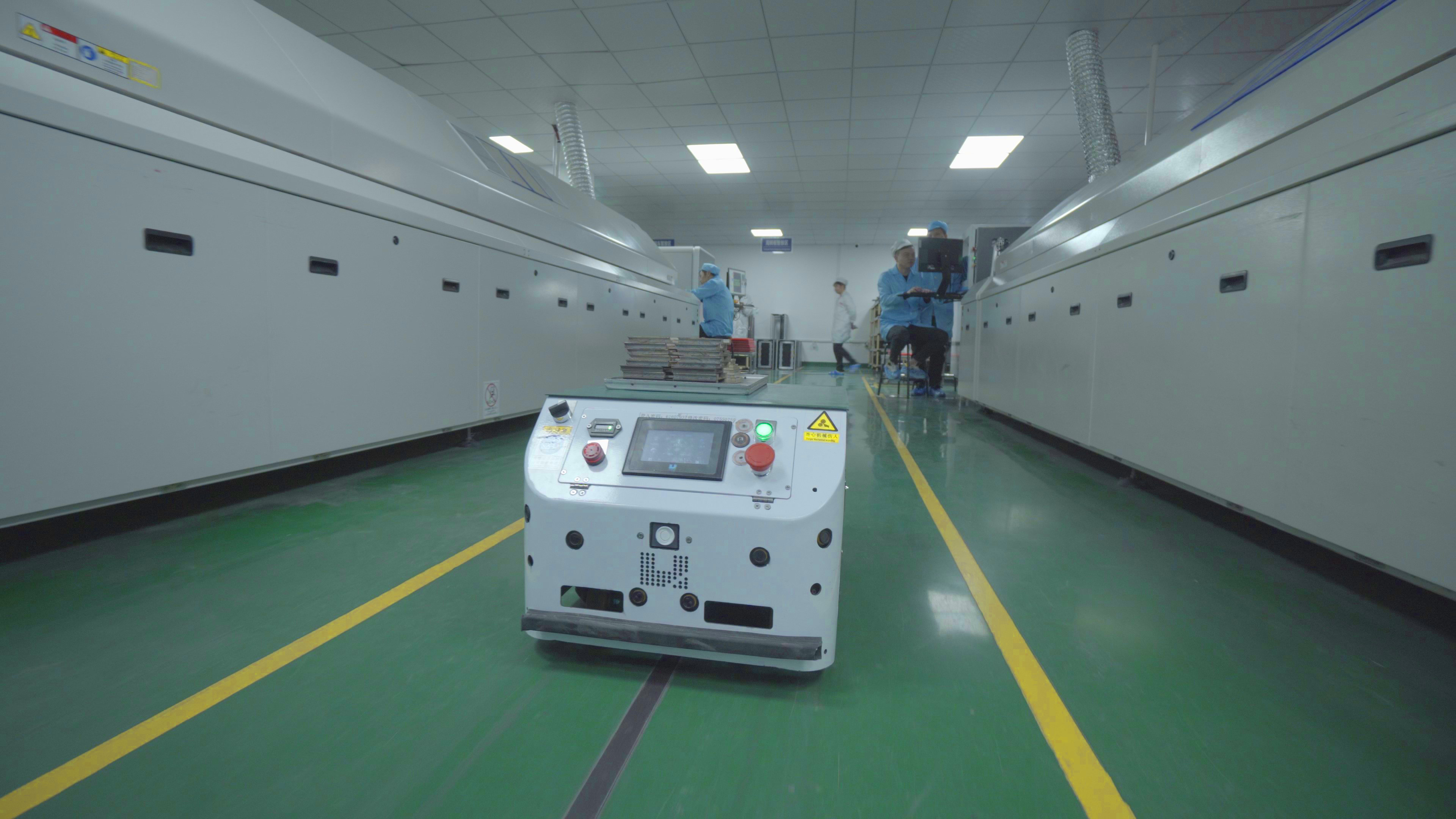
SMT, standing for surface mount technology, refers to the process of mounting electronic components like resistors, capacitors, transistors, and integrated circuits onto the surface of a printed circuit board (PCB) in electronics. It was first invented in 1960 by IBM and then was widespreadly applied in high-tech electronic PCB assemblies. The electronic component mounted during the SMT assembly line is the so-called surface mount device (SMD).
There are several forms of surface-mounted assemblies. One is the single-line form, which occurs when only a single layer of the PCB is needed to be assembled. However, if we need to assemble SMC or surface-mounted devices on both sides of the PCB, we should have a two-line SMT production line. Sometimes the PCB components placement will exist in many places, in which case adding an extra interposing assembly line could be necessary. The interposing assembly line will be based on the original PCB SMT assembly line.
 About PCBasic
Time is money in your projects – and PCBasic gets it. PCBasic is a PCB assembly company that delivers fast, flawless results every time. Our comprehensive PCB assembly services include expert engineering support at every step, ensuring top quality in every board. As a leading PCB assembly manufacturer, we provide a one-stop solution that streamlines your supply chain. Partner with our advanced PCB prototype factory for quick turnarounds and superior results you can trust.
Although the SMT approach has made the production of electronic boards more accurate and faster, not all components can be surface-mounted onto the top of PCBs. The components suitable for SMT lines are often smaller. Hence, there is still a need for the old through-hole technology (THT).
The THT components are bulky with axial or radial leads and need manual assembly. The process is finished by inserting the leads into drilled holes on the circuit boards and soldering them in place. Even though SMT lines are more popular, the THT components will work as well as SMD in many cases, sometimes even better.
In addition, there is a case in which both THT and SMT assembly lines are required, known as a hybrid assembly. The inserts and mountings are combined to consist of the hybrid production line.
What processes does an SMT production line include? It’s necessary to understand the SMT assembly line process before choosing a good SMT service provider. The general process of a single-form SMT line includes the following steps:
Material preparation and inspection is the very first step of the SMT line in our PCB assembly factory. QC inspectors should carefully examine the PCB and SMT components for any flaws and pick out unqualified materials. At this stage, these circuit boards are flat with solder pads.
This step is to print the solder paste or patch glue on the SMT stencil to prepare for the soldering of the SMT components. Since the solder paste plays an essential role in connecting the components to the printed circuit board, the paste used in our PCBasic factory is provided by MacDermid Alpha, a leading company in making high-quality solder pastes, to ensure the electrical performance of the board.
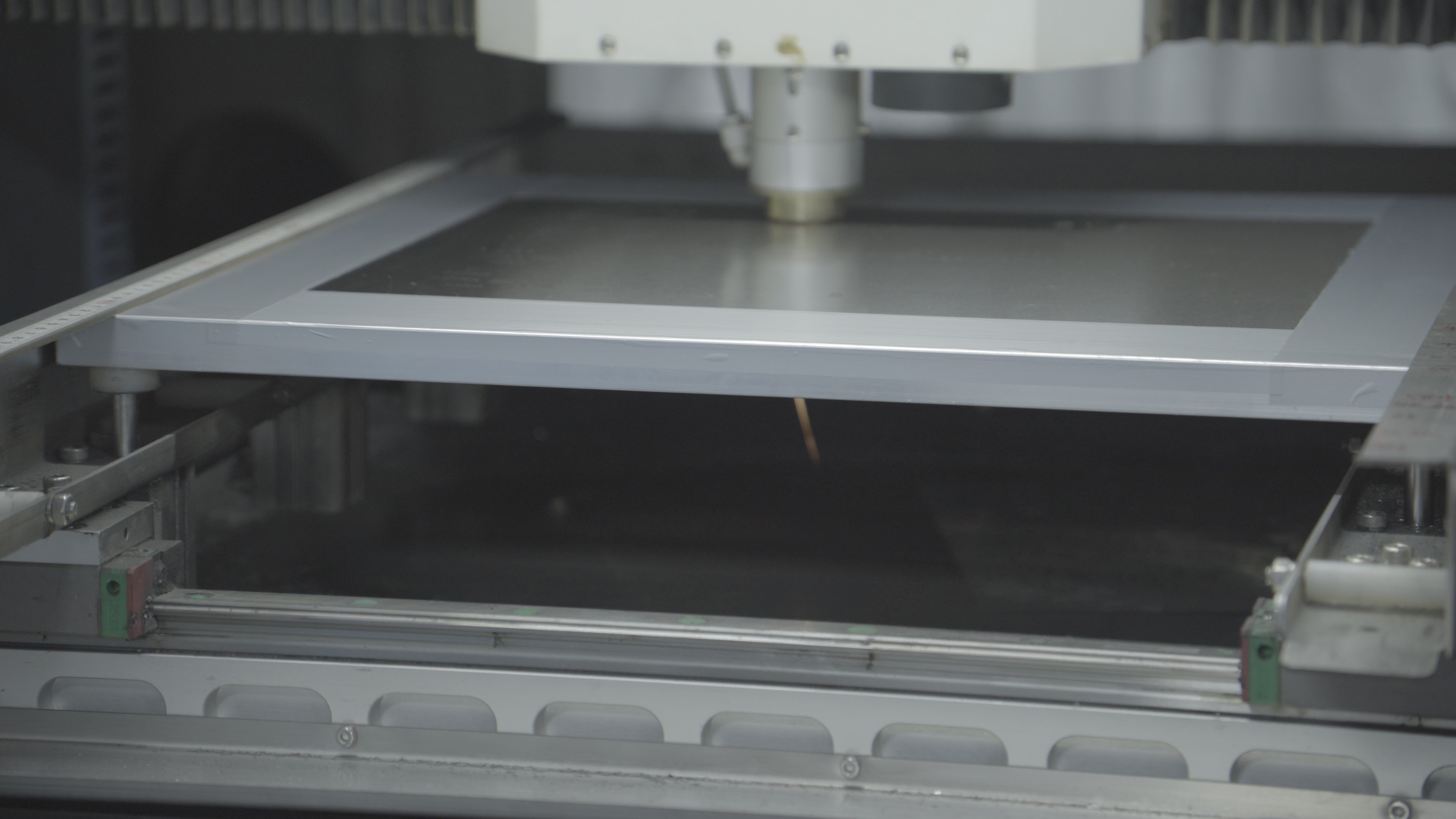
After entering this stage, the glue dispenser is used to drop glue onto the fixed position of the SMT stencil. Its main function is to fix surface-mounted components on the PCB when wave soldering is used. Therefore, a solder paste inspection (SPI) should be conducted after dispensing.
The next step in the SMT line is to mount the surface-mounted components onto the solder-printed PCB with a pick-and-place machine. The pick-and-place equipment picks up the electronic components and places them on board. The process is fully automatic to avoid errors caused by humans.
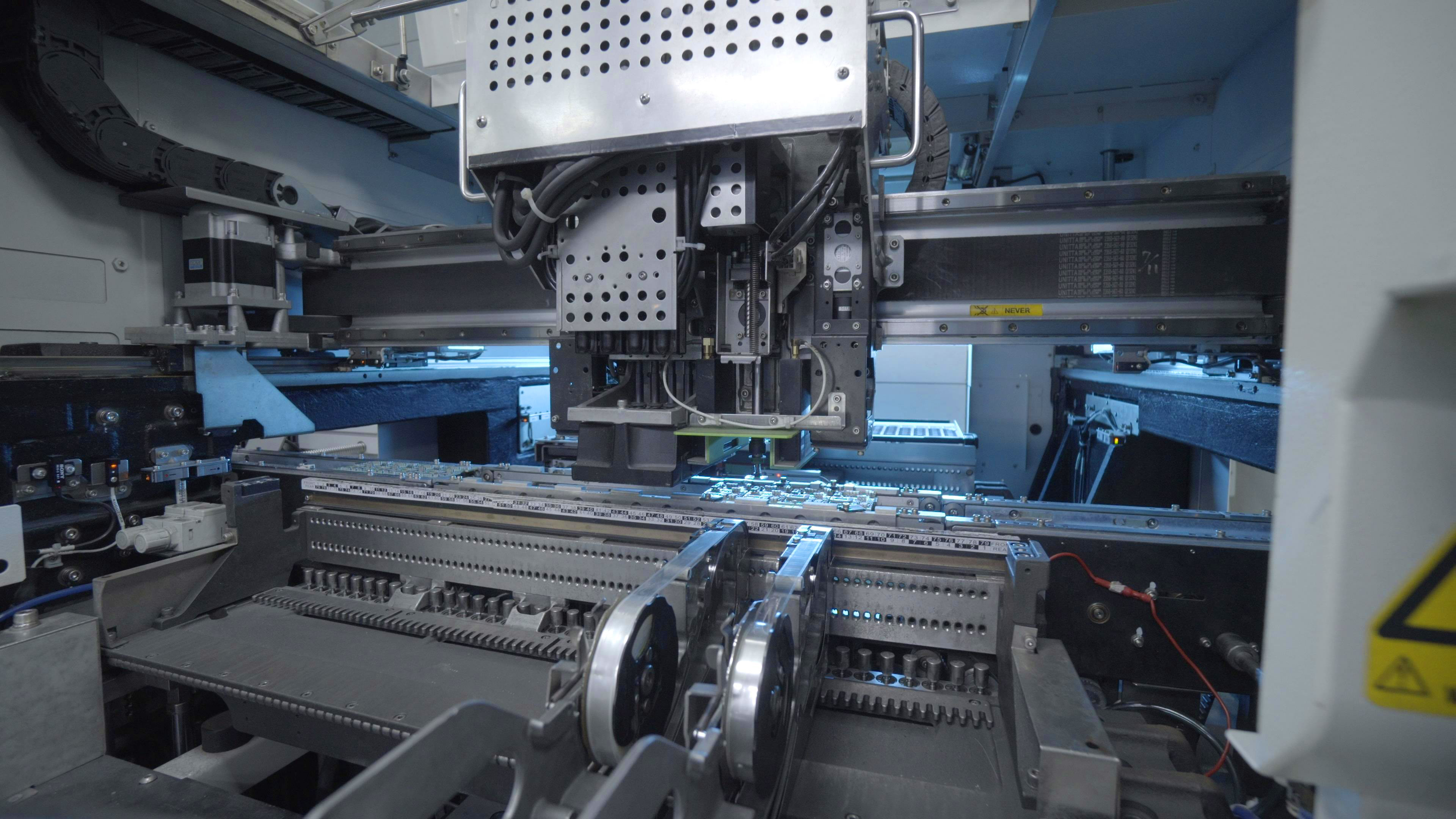
After the component placement process, the surface-mounted boards move to the glue curing station, which is a vital process in the SMT production line. Operators cure the SMD glue in a curing oven so that the surface assembly components and SMT stencil are firmly bonded together.
The solder paste is melted in this stage to enhance the components bonding to the board. The complete reflow soldering process in the SMT line consists of four stages, namely four temperature zones (the board should be placed into the reflow oven first) :
Stage 1: The preheat zone, where the temperature of the surface-mounted device and the board ascend gradually. The temperature in the oven climbs by around 1-2 ℃/s before it arrives at 140-160 ℃.
Stage 2: The soaking zone, where the oven temperature holds steady at 140-160 ℃ for around 90 s.
Stage 3: The reflow zone, where the temperature begins to reascend at a rate of 1-2 ℃/s until it reaches the peak (210-230 ℃), radiating enough heat to melt tin in the solder paste and thus to bond each component to the board.
Stage 4: The cooling zone, where the weld is frozen to avoid welding defects.
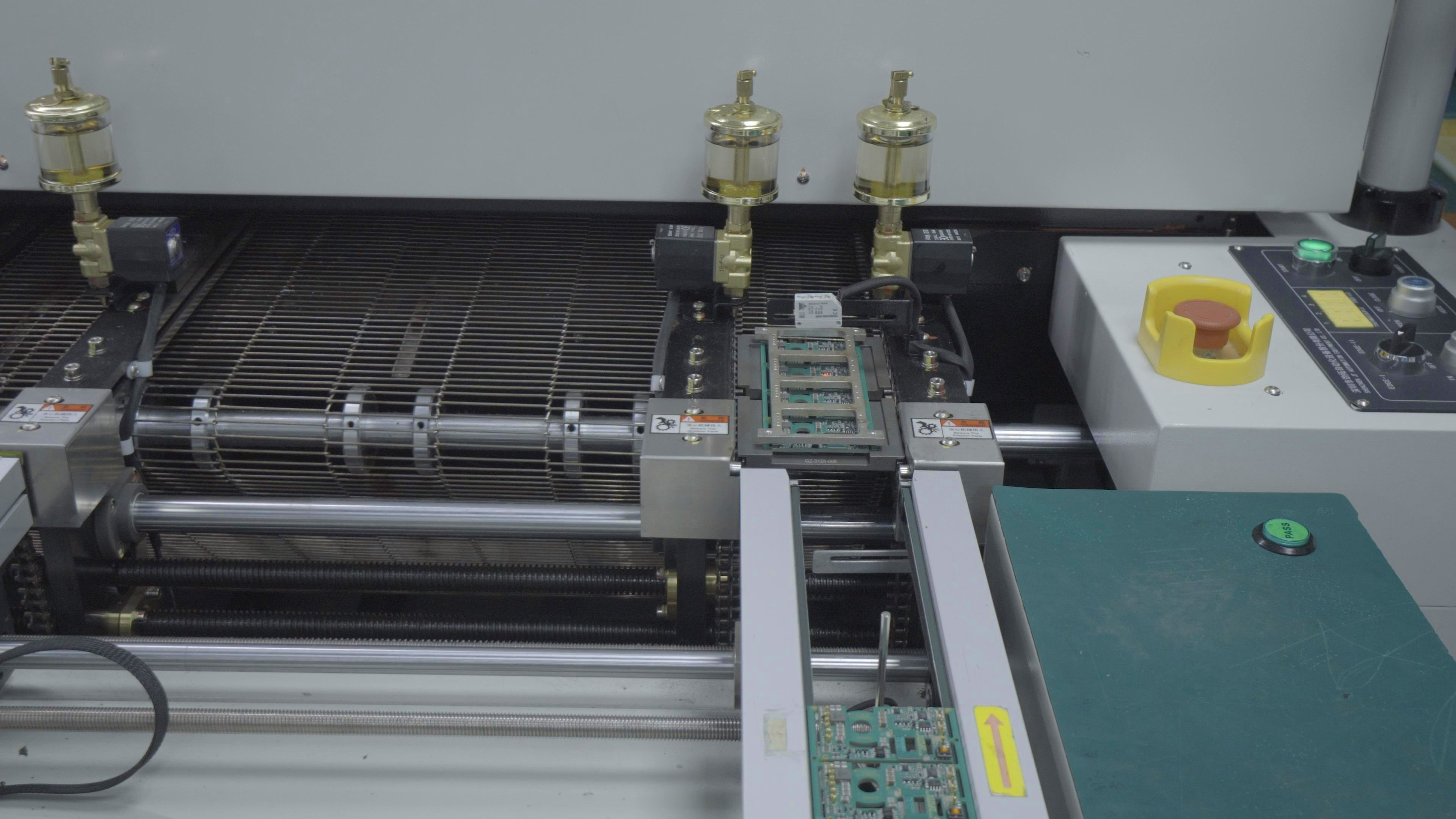
Next, the assembled PCB heads to the cleaning stage in the SMT line to remove the solder residues, such as flux and any other material harmful to the human body. A cleaning agent is used to finish the process. However, if the no-clean welding technology is applied, this process is not necessary.
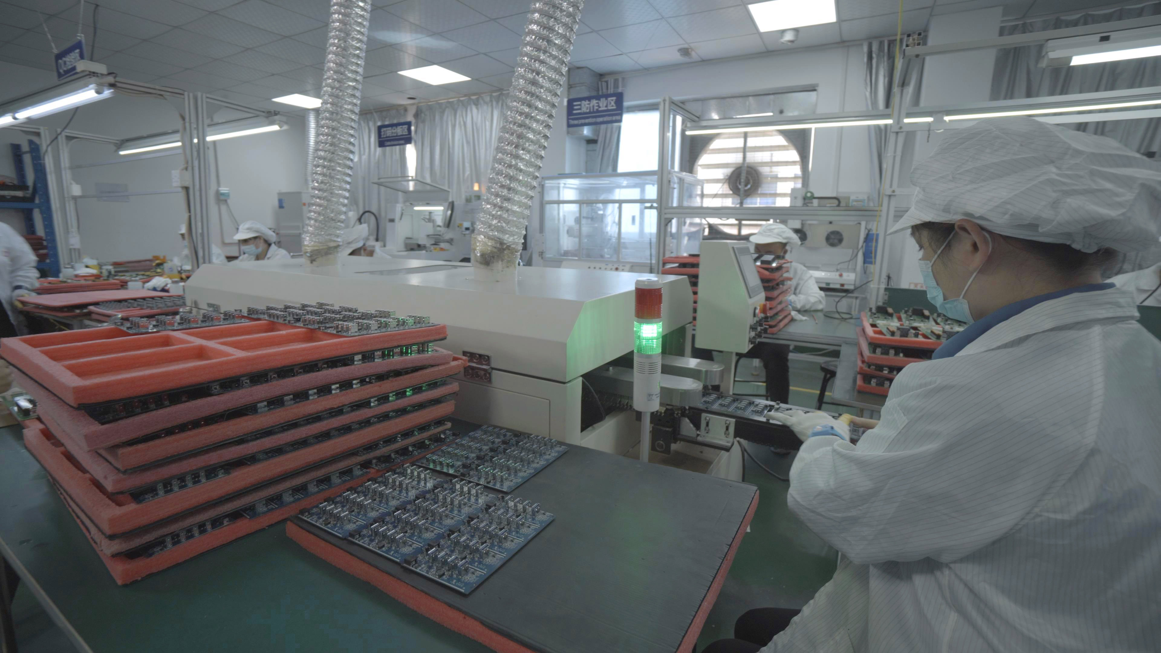
The final step in a normal SMT line is inspection. PCBasic uses a variety of tools to inspect the actual quality (i.e., welding and assembly quality) of the finished printed circuit board. The specific inspection items depend on clients’ needs, commonly including automated optical inspection (AOI) by a microscope, X-ray inspection by SMT X-ray equipment, visual inspection, performance inspection by online testers and first article testers, and many more.
In addition, our factory has invented the first SMT article tester to increase testing accuracy and efficiency. The tester can automatically determine if the article is qualified and import the testing data to our system. Hence, operators don’t have to make any judgment, which avoids possible human errors.
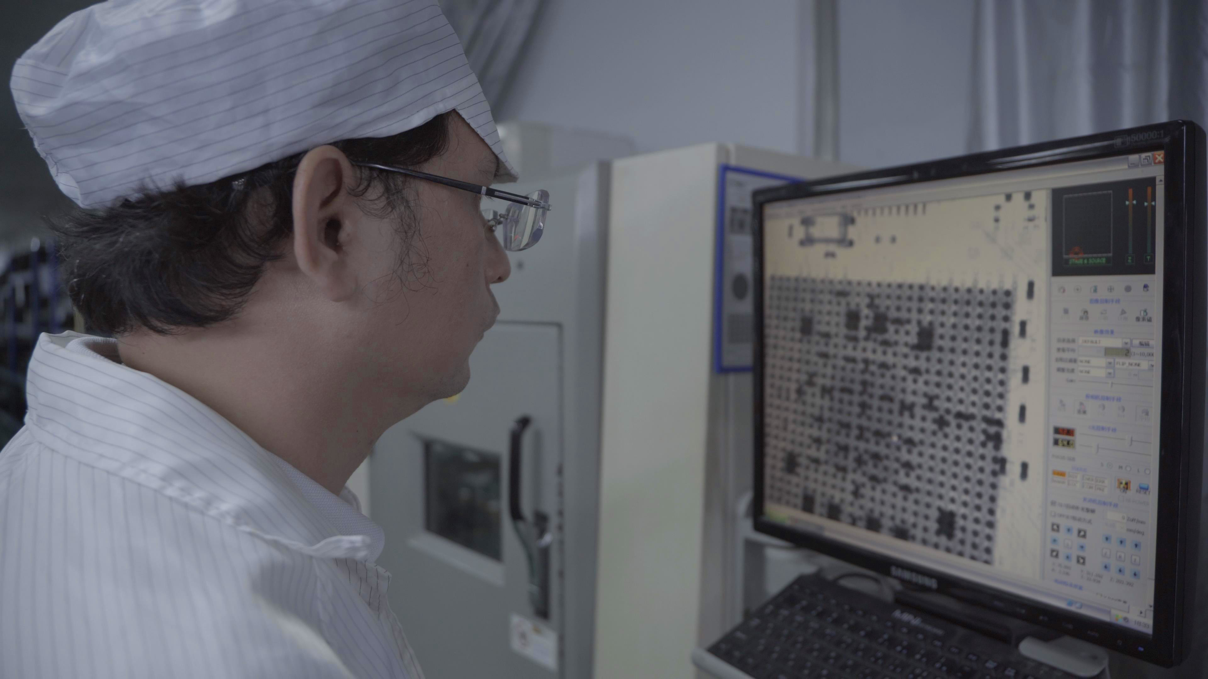
The repair step is followed when defects are found. No defects, no repair. The tools used here are electric soldering irons, rework stations, etc. The step is configured anywhere in the SMT line. The repaired PCBs will be rechecked to guarantee quality and performance.
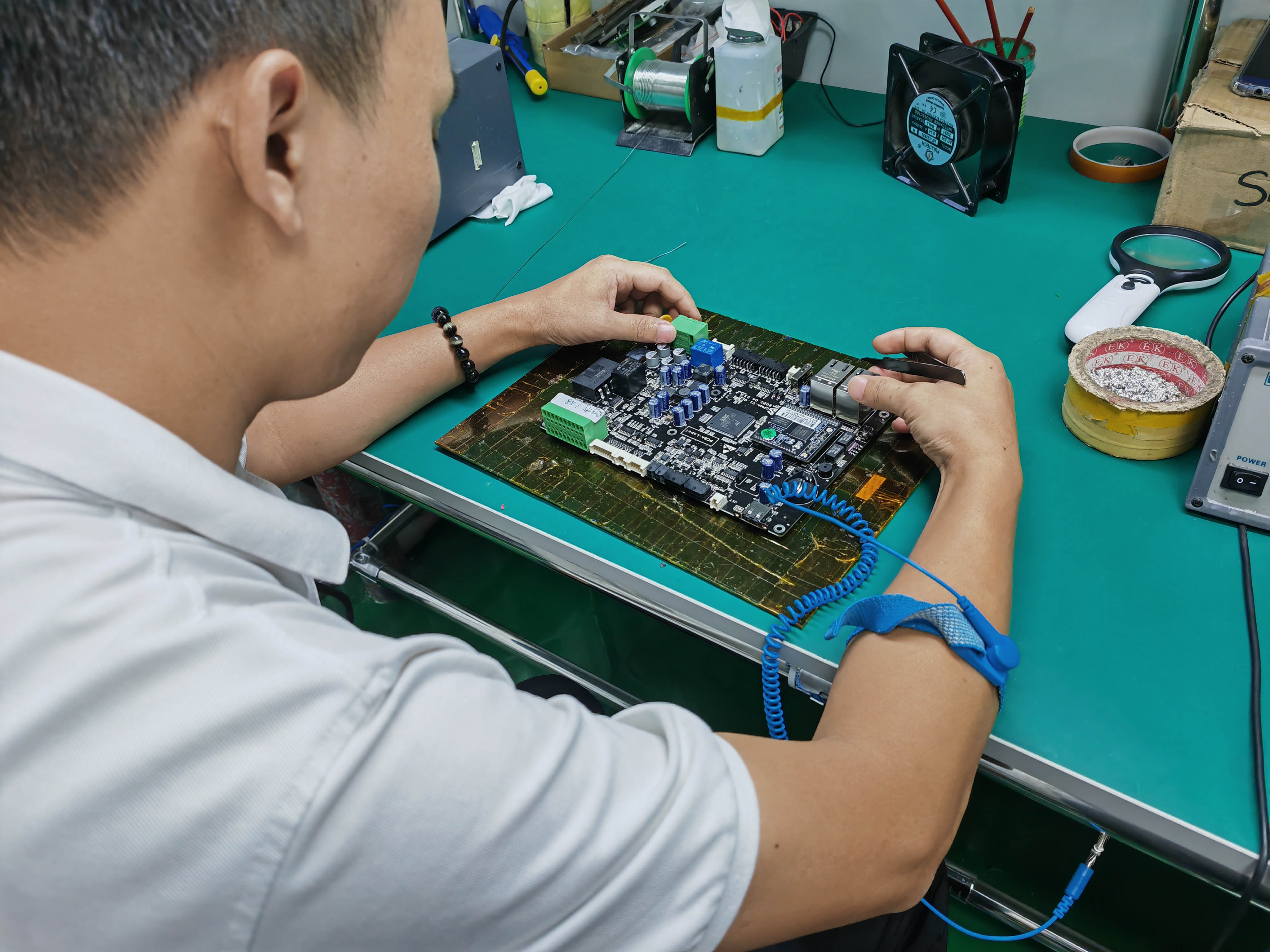
A surface mount technology production line has different elements working to assemble electronic components to PCB boards. These elements or machines ensure the high efficiency and effectiveness of SMT lines in our factory. Here is a list of equipment used in our SMT production line:
1. Stencil Printer: The stencil printer is used for the application of solder paste on the PCB board. The stencil has openings according to the solder pads on PCB boards, and solder paste is applied through these openings.
2. Pick-and-Place Machine: This machine gets electronic components from trays, reels, or tubes and properly places them on solder paste on board. Currently, used pick-and-place machines are highly automated and have the ability to handle different component types and sizes.
3. Reflow Oven: A reflow oven is used for component soldering on boards. The board with components and solder paste faces the controlled heating process in a reflow oven, where the solder paste melts to make reliable solder joints.
4. Conveyor System: Through the conveyor, boards move through every step of the SMT line from the stencil printer to the pick-and-place machine and reflow over. It provides a continuous production flow.
5. Solder Paste Inspection (SPI): SPI is used for the inspection of solder paste deposition quality on board before component configuration. It helps to find problems like ineffective solder paste and misalignment and increases overall solder joint quality.
6. Component Placement Inspection (AOI/AXI): Automated Optical Inspection (AOI) and Automated X-ray Inspection (AXI) systems inspect the component's configuration when they are connected on board. AOI techniques use cameras to inspect the errors, and in AXI, X-rays are used for the inspection of hidden joints, like in BGA.
7. Reflow Profiling Equipment: Reflow profiling instruments check and make sure that the reflow oven is following the accurate temperature values that are important for accurate solder joint creation without affecting sensitive components.
8. Conformal Coating or Underfill Dispensing (Optional): Some SMT lines come with the station to apply a conformal coating or underfill to protect components and increase their reliability in harsh environments.
9. Quality Control Stations: At these stations, there can be functional testing, manual inspections, and different measurements to make sure that the assembled boards fulfil quality and performance standards.
10. Traceability System: The data of the board is recorded by the traceability system; this information includes soldering features, component placement, inspection outcomes, and other parameters. It is helpful to find and solve different problems if they exist and offer a record of the manufacturing process of SMT line.
11. PCB Handling and Storage: Accurate handling and storage parameters are important to avoid contamination, static discharge, and damage during assembly.
12. Workstations and Operator Stations: These features offer operators space to load components onto feeders, monitor the assembly process, and solve issues if they exist.
13. Data Management and Programming: Software systems control the programming of reflow ovens, pick-and-place machines, and inspection instruments. With that, they maintain production data and help with process improvement.
14. Material Management: In this process, there is the management of components such as reels, tubes, trays, and other packaging materials to ensure a steady supply for manufacturing.
15. Environmental Control: Different parameters such as humidity, temperature, and cleanliness are important to maintaining consistent production quality and avoiding faults.
There are different types of Surface Mount Technology (SMT) production lines, and every type is made to optimize different parameters of the assembly process, such as flexibility, efficiency, and space use.
1. In-line Layout (Linear Layout): In an in-line layout, the working area and machines are configured in a linear configuration, where the board is moving in a single straight line through different phases of assembly. Its compact and simple layout makes it best for small productions. But it can be less flexible to handle different boards and configurations.
2. U-Shaped Layout: A U-shaped layout configures machines and working areas in a U-shape. This design helps to provide flexibility to handle different board sizes and structures than the in-line layout. It can also offer good visibility and access for operators.
3. L-Shaped Layout: This layout makes an L-shape for machines and working areas. This design is mostly used where space is limited and makes good use of the provided areas. It can be good for high production volumes.
4. Cellular Layout: In a cellular layout, the production line is configured into cells, each doing a certain operation or process. This layout is flexible and can handle different production needs. It is good for customized or low-volume productions.
5. Turret Layout (Star Configuration): In this layout, the pick-and-place machine is configured in the centre, and other machines and working areas are configured in circular or star-like arrangements about them. It is best for high-speed production and provides effective material flow from central machines.
6. Dual Lane Layout: This layout comes with two parallel lines for the board to move through the production process. This layout increases manufacturing features by providing two boards to be processed at the same time. It is mostly used for high-volume production.
7. Modular Layout: In a modular layout, the production line is created with the use of modular units that can be easily configured and expanded when required. This layout type provides adaptability and scalability to meet varying production needs.
8. Mixed Layout (Hybrid Layout): A mixed layout links different components from different layout types to optimize certain parameters of manufacturing. For instance, it can be used as a U-shaped layout for pick and place and a linear layout for the inspection and soldering processes.
SMT Lines come with massive advantages as compared to traditional PCB assembly processes. These are:
SMT line provides the larger component density on the printed circuit board since components are directly mounted onto the board surface. That makes the small-sized and compact devices and projects considered the main part of modern electronics. Therefore, we now have efficient and compact devices like smartphones.
High compact density makes the finished products smaller and less weight, which is good for portable and wearable devices where space is the main factor.
SMT line is a highly effective and automated PCB assembly process. In this technique, components are configured on board. The use of pick and place machines in SMT provides faster assembly and production.
There is less use of manual labor in the SMT assembly process. The traditional PCB assembly approach (through-hole technology) requires manual insertion and component soldering, which is time-consuming and may cause errors.
SMT components (SMD) are mostly configured close to the surface of the board, providing smaller interconnection lengths. This ensures less parasitic capacitance and inductance and improves the electrical function of circuits.
The smaller interconnection lengths and less parasitic factors of an SMT production line can bring good signal integrity, less electromagnetic interference, and good high-frequency performance.
With less cost for SMT instruments, the total costs of production decrease due to faster assembly, less manual labor cost, and wastage of fewer materials.
Compared to the THT assembly process, SMT lines are more automatic because most equipment used in the SMT assembly is fully automated with no manual handling, greatly shortening the production cycle and enhancing assembly efficiency.
Direct surface-mounted components dissipate heat effectively. So, it’s best for components that produce high heat during work.
SMT process is also preferred for advanced technologies such as Ball grid array packages, fine pitch components, and multi-chip modules, helping to provide the production of cutting-edge devices.
There are different types of components supported by resistors, integrated circuits, capacitors, and other electronic components, making SMT line the best for different types of electronic projects and devices.
There is less solder used in the SMT line. The less energy consumption and waste of hazardous materials make the production line more environment friendly.
As an experienced PCB assembly factory in Shenzhen, China, PCBasic has invested massive money and effort to build a leading SMT production line for better PCB assembly. The antistatic flooring and precise temperature and humidity control create a perfect environment for the SMT line, while the advanced SMT equipment guarantees production efficiency and quality.
The SMT line in PCBasic is fully automatic with 13-step circuit board testing procedures. Thorough inspections are conducted at each necessary station to prevent defective boards from flowing into the next station.
To speed up the production process and deliver products quicker to clients, the feeding trolleys are used to control and manage the surface-mounted components by computer, ensuring the components are most efficiently arranged to minimize the travel time.
As more and more people look for slim and compact devices, the role of SMT lines in electronics becomes increasingly prominent. We hope this article has offered some insights into the process occurring in the SMT line. If you have any comments or questions, please let us know.
Assembly Enquiry
Instant Quote
Phone contact

+86-755-27218592
In addition, we've prepared a Help Center. We recommend checking it before reaching out, as your question and its answer may already be clearly explained there.
Wechat Support

In addition, we've prepared a Help Center. We recommend checking it before reaching out, as your question and its answer may already be clearly explained there.
WhatsApp Support

In addition, we've prepared a Help Center. We recommend checking it before reaching out, as your question and its answer may already be clearly explained there.
