Global high-mix volume high-speed PCBA manufacturer
9:00 -18:00, Mon. - Fri. (GMT+8)
9:00 -12:00, Sat. (GMT+8)
(Except Chinese public holidays)
Global high-mix volume high-speed PCBA manufacturer
9:00 -18:00, Mon. - Fri. (GMT+8)
9:00 -12:00, Sat. (GMT+8)
(Except Chinese public holidays)
HomePage > Blog > Knowledge Base > Reflow Soldering Vs Wave Soldering: An Ultimate Guide
Soldering is widely used in making PCBs and is very important. It is employed to fix electronic parts to printed circuit boards. The PCB industry mainly employs two processes, namely, reflow soldering and wave soldering. Both of these are useful and have their merits. It is, therefore, necessary to choose the proper method that will assist in attaining the production objectives, cost control, and general manufacturing objectives.
This article provides information on the comparison of reflow and wave soldering. The awareness of each method makes it possible to determine which method should be applied. As a manufacturer or an engineer, you can make the right choices in improving your PCB manufacturing plan with this guide.
Reflow soldering is the most popular method of mounting devices on the surface of PCBs. This process differs relatively from wave soldering, mainly in terms of through-hole components. Wave soldering is cheaper than reflow soldering, even though the former is used primarily on through-hole components.
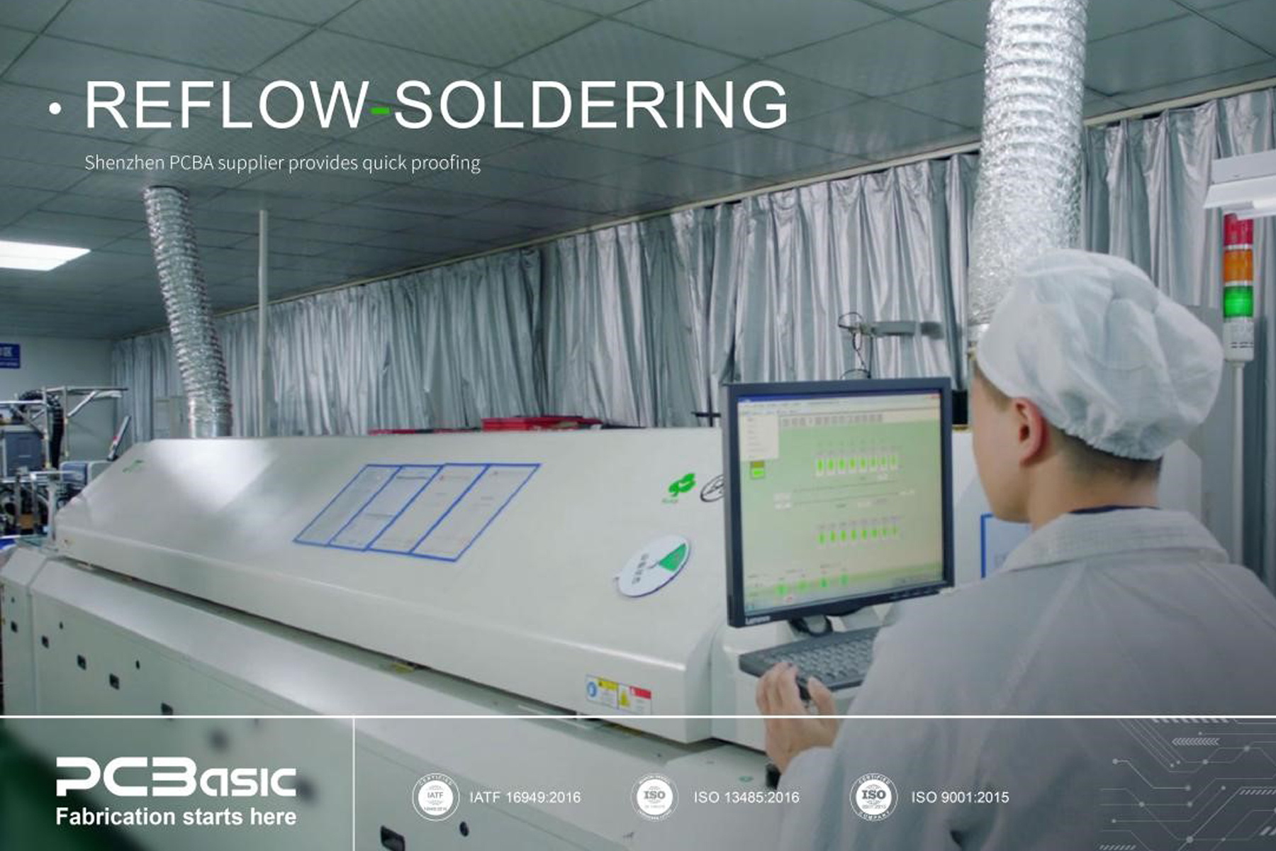
Fine powdered solder and fluxes are applied in reflow dip soldering by mixing them with the contact pads' components. The assembly is then taken to an infrared lamp to allow the solder to melt and make strict connections. In case of necessity, the individual joints can also be soldered with the help of a hot air pencil.
The only significant difference between reflow and wave soldering is how heat affects the PCB. In reflow soldering, heat is applied from the top with the help of equipment in a very controlled manner. Wave soldering is usually done on the bottom side of the printed circuit board. The components are inserted by hand, and the surfaces are pressed so that they fuse. Also, reflow soldering is more accurate and precise than wave soldering because the process has more control over it.

Reflow soldering is one of the fundamental procedures in electronics manufacturing to mount components on printed circuit boards (PCBs) using solder paste. Here are the most common steps involved in its process.
The preliminary step is preheating, where the PCB assembly is heated slowly to prepare it for soldering. This step has two general objectives:
Thermal Profiling: This ensures that the PCB reaches the proper temperature appropriate for soldering throughout the circuit assembly.
Solvent Evaporation: Preheating helps expel volatile solvents in the solder paste. Further, these solvents can influence the soldering process and decrease the dependability of the soldered connection.
Then, it's succeeded by the thermal soak phase of the assembly in case preheating has been done. In this stage, the temperature is maintained to make the flux in the solder paste work. Flux must be activated because it typically improves the wetting between the solder and metal, which is vital in forming good solder joints.
In the reflow soldering phase, the paste melts and wets the component leads and the PCB pads to create metallurgical bonds. This process generally involves:
Ramp-up: Regulation of the temperature to the maximum reflow temperature to determine the quantity of heat supplied to the solder paste.
Soak: Soak helps the assembly stay at the highest temperature for a while, allowing the solder to melt and flow.
Cooling: The last reflow is the quenching. Here, the temperature is brought down rapidly to make the solder joints solidify and fix the components on the PCB.
The last process carried out when reflow is done is the cooling of the assembly. Controlled cooling is critical to: It is therefore necessary to regulate the rate of cooling to:
Make sure you have good mechanical and electrical contact with the molten solder.
Thermal shock should never be applied to the circuit in any way that impacts the components or solder joints.
Ensure that the connections developed through soldering are as solid and durable as possible.
The reflow soldering process employs solder paste, referred to as the reflow solder paste. It contains the paste of solder alloy powders and a fluxing agent. It's deposited on the PCB assembly through screen printing, reflowed, and solidified to make solder interconnections.
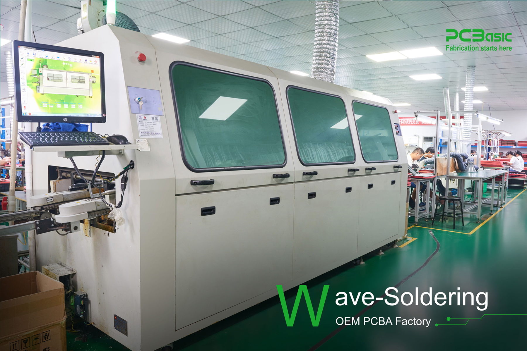
Wave soldering is another method applicable soldering method in PCB manufacturing. It's a more adequate technique for engineers who require many PCBs to be soldered simultaneously. The wave soldering process starts with the application of flux on the components that are to be soldered. The flux removes the oxide layer and cleans the metal before soldering, which is an essential quality work process.
Subsequently, as in the case of reflow soldering, preheating occurs to prevent the effects of thermal shock during the precise soldering process. The solder will wave over the PCB and start soldering the various components; electric connections are made at this stage. A cooling technique is then applied. It helps minimize the temperature, solidify the solder, and fix it in place.

The use of flux in wave soldering is essential to produce clean and strong solder interconnections on the printed circuit boards. The flux helps to clean the metal surface to prevent any present formation of any oxide layer. Therefore, it prevents the solder from wetting the surface adequately. This way, the flux removes the oxides that hinder the interaction between the pins and boards. Additionally, it minimizes the drag coefficient affecting the electrical connections.
Furthermore, flux contributes to reducing the oxidation of the PCB during the heating process, so the soldering process will continue as planned. Also, it must improve thermal conductivity so that all the components are well-soldered. In addition, the flux should be compatible with the application to prevent damage to the components by an incompatible solvent.
PCBs are first exposed to heat in a heat tunnel conveyor system before they are exposed to waves of molten solder. This step is critical as it initiates the flow applied on the surface of the PCB. The soldering process requires the solder to form a good bond with the components, which is made possible by activated flux. Preheating also helps reduce moisture on the PCBs, which would be a problem when soldering. Preheating is gradually heating the PCBs to avoid thermal shock, which is detrimental to the solder joints. Moreover, it preheats the PCBs in preparation for the soldering process to the right temperature suitable for soldering.
Here, the solder is applied in a controlled wave on the surface of the PCB. When heated, the solder paste on the board becomes a liquid and forms a wave of solder. This wave mainly passes over the PCB, joining components to the board and making stable electrical connections. Besides attaching the elements to the PCB, the molten solder gives mechanical support and electrical insulation to the joints.
PCBs are then cooled to allow the solder joints to cool, harden, and set the components. Cooling is essential because it helps avoid deformation of the PCBs due to the heat left on them. The specified temperature is lowered slowly so the solder joints can solidify and make a firm connection. It ensures that the connections made during wave soldering are strong and can endure heat and vibrations. Through controlled cooling, the manufacturers can guarantee the integrity of the soldered joints and, thus, the quality of the PCB assembly.
Soldering of PCB affects productivity and expenses. Reflow soldering and wave soldering are different in the way they apply flux. In the process, flux removes the oxide layer from the surface of the metal before molten solder is poured over the PCB. This creates electrical connections relatively fast. In reflow soldering, solder paste contains flux that is built into it. It is baked in an oven for proper adhesion of the copper foil to the fiberglass weave without having to solder the entire board.
Wave soldering is used for components that do not have a large area of contact with the PCB. In comparison, reflow soldering is used for components with a large contact area with the PCB. It's suitable for through-hole components and soldering the boards in a single pass at a swift rate. Reflow soldering suits smaller and closely pitched SMTs or surface mount devices. Mixed strategies are used for boards with different parts, and both methods are used here.
Wave soldering is ideal for large-scale production due to the constant solder flow. Reflow soldering, on the other hand, is suitable for applications requiring fine soldering for a few products. The project volume and its specifics determine the type of method chosen.
Wave soldering involves using a molten solder wave as a single pass for board soldering. Contrastingly, reflow soldering uses heat to melt solder paste on the PCB but does not overheat the components and small parts. Moreover, the flux is incorporated into the solder paste in reflow soldering. Therefore, there is less wastage than wave soldering, which applies flux broadly.
Professionals in engineering make selection decisions depending on the intended project's requirements. The high accuracy of reflow soldering makes it ideal for SMT components with regulated temperature characteristics. Wave soldering, in contrast, is relatively faster and cheaper for through-hole components. Because it only needs a little complex equipment. The medium solutions combine high efficiency and joint quality for mixed-component PCBs.
Reflow soldering is used to solder small parts on the PCBs. It involves solder paste and incorporates the right temperature to guarantee good connections. While it initially entails a certain level of investment because of equipment, it has short cycle times and produces joint solid connections. Temperature control during reflow is crucial to avoid defects and achieve optimal results.
In contrast, wave soldering is frequently used to solder multiple PCBs in the shortest time. It entails dipping PCBs over a wave of molten solder, which effectively solder through-hole parts. However, it's not recommended for delicate or small SMD components because of its less accurate placement. Additionally, wave soldering produces more soldering scrap, and more attention needs to be paid to the flux to avoid soldering problems such as bridging or forming cold joints.
Reflow soldering is widely used in SMT for electronics such as smartphones, computers, and other consumer electronics. Product designers prefer it because it quickly positions small components like microprocessors and resistors on the PCBs. However, THT assembly commonly applies wave soldering for connectors, switches, and other large electronic parts. Moreover, the method is valuable in applications that require mechanical solid interconnections since it involves using leads fitted into holes drilled beforehand on the PCB.
The type of soldering method to be used in PCB assembly depends on some crucial factors. Reflow soldering is usually applied when the assemblies are used primarily with SMT components. It allows the placing and welding of delicate parts like microchips and capacitors used in circuit manufacturing.
As for the assemblies with through-hole components, called through-hole technology (THT), it is possible to wave-solder. This technique helps achieve suitable components soldering with the leads inserted into the drilled holes on the PCB and good mechanical connections.
A mixed solution might be needed in cases where the assembly contains both SMT and THT parts. This involves improving reflow soldering for the surface mount technology parts and wave soldering for the through-hole parts to strengthen the two techniques. The applicability of each method also depends on the production batch, the cost, and the characteristics of the PCB layout.

This article compares two soldering techniques, namely reflow soldering and wave soldering. It describes procedures and temperatures for each. Reflow soldering will be described in simple steps that engineers and tech companies will find helpful. The tools required for the process are mentioned at the end. Although reflow ovens are used, others, such as skillets, are possible. The reflow soldering process is susceptible to temperature rise and oven settings in which the printed circuit boards are to be heated. Solder paste is also essential and should be of the best quality.

Assembly Enquiry
Instant Quote
Phone contact

+86-755-27218592
In addition, we've prepared a Help Center. We recommend checking it before reaching out, as your question and its answer may already be clearly explained there.
Wechat Support

In addition, we've prepared a Help Center. We recommend checking it before reaching out, as your question and its answer may already be clearly explained there.
WhatsApp Support

In addition, we've prepared a Help Center. We recommend checking it before reaching out, as your question and its answer may already be clearly explained there.
