Global high-mix volume high-speed PCBA manufacturer
9:00 -18:00, Mon. - Fri. (GMT+8)
9:00 -12:00, Sat. (GMT+8)
(Except Chinese public holidays)
Global high-mix volume high-speed PCBA manufacturer
9:00 -18:00, Mon. - Fri. (GMT+8)
9:00 -12:00, Sat. (GMT+8)
(Except Chinese public holidays)
HomePage > Blog > Knowledge Base > PCB Diodes: A Comprehensive Guide
The diode is one of the most fundamental and commonly used semiconductor components in electronics. It is widely used in simple power circuits to complex signal processing systems. So, what is a diode? What types does it have? what does it do in the circuit? If you don't know, don't worry. Today, we will introduce to you the relevant knowledge about PCB diodes. First of all, let me introduce to you what a diode is.
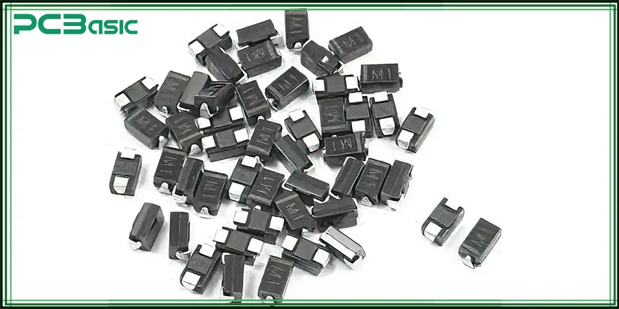
A PCB diode, simply put, is a double-ended device composed of P-type and N-type semiconductor materials. It has unidirectional conductivity - that is, it allows the current to flow from the anode to the cathode but prevents the current from flowing in the opposite direction. This is the most important characteristic of diodes. This characteristic makes diodes key devices for managing voltage, protecting components and controlling the flow of signals. All the diodes used in PCBs have the same basic characteristics:
Only allow the current to flow in one direction
Prevent current backflow or voltage surges
Polarity sensitive
The polarity sensitivity of PCB diodes means that they must be installed in the correct direction. The direction can usually be determined by the polarity marking on the PCB and the identification on the device body. If the installation direction is incorrect, the diode may not work properly and may even damage the entire circuit.
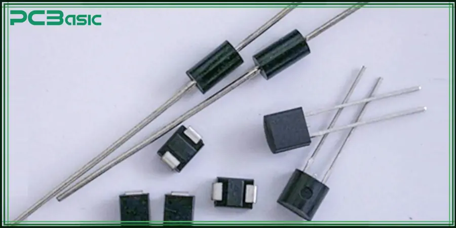
On a PCB, diodes usually adopt two packaging forms: Through-Hole and Surface-Mount Device.
Through-hole packaging: The diode pins pass Through the holes on the PCB and are fixed and conducted through the pads. The advantage of this package is its high mechanical strength, ease of manual soldering and maintenance. It is suitable for components with high current or large volume, and is commonly found in industrial power supplies, transformers, automotive electronics and other scenarios with high requirements for firmness.
SMD packaging: Diodes are directly soldered onto the pads on the PCB surface without the need for perforations. The advantages of this packaging are its small size, light weight and suitability for automated production. However, special attention should be paid to the polarity marking during installation to ensure the correct direction of the current.
Diodes play multiple key roles in PCB circuits. Including: ①The rectification function of converting alternating current to direct current; ②Voltage regulation through a voltage stabilizing diode; ③ TVS or Zener diodes are used for clamping and ESD protection. ④ In digital circuits, it is used for signal control and logic guidance, as well as for light emission and light sensing through LEDs and photodiodes. These functions cover multiple aspects ranging from power management to signal processing.
In short, the diode on the PCB is not only a basic component, but also one of the core parts that ensure the reliable, safe and efficient operation of electronic circuits.
Understanding the working principle of diodes, polarity identification and the marking method on PCBs is the key to the normal operation of circuits. The following are several working modes of diodes:
Forward bias - Conduction mode
Under forward bias, the anode is connected to the positive terminal of the power supply, and the cathode is connected to the negative terminal. This will reduce the potential barrier of the junction and allow the current to conduct through the diode. The direction of the diode symbol is: the current enters from the triangle (anode) and exits from the vertical line (cathode).
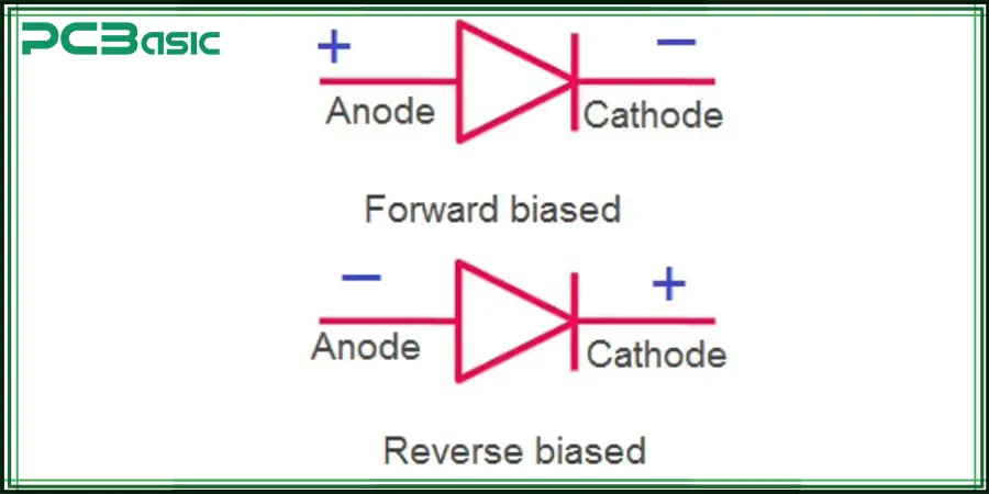
Reverse bias - Cut-off mode
Under reverse bias (where the cathode voltage is higher than the anode), the depletion layer widens, and the diode blocks the flow of current: it does not conduct electricity, only has a small leakage current, or appears in an open state in the PCB to prevent damage caused by reverse current.
Breakdown area - Special purpose
When the reverse voltage exceeds a certain threshold, the diode enters the breakdown region. Not all diodes can withstand breakdown. Only certain types of diodes (for example, voltage stabilizing diodes and avalanche diodes) can operate normally in this state.
In modern electronic circuits, different types of diodes perform various functions, ranging from rectification and voltage regulation to protection, display, and signal control. The following are several common types of diodes used in PCBs in electronic devices:
1. Rectifier diode
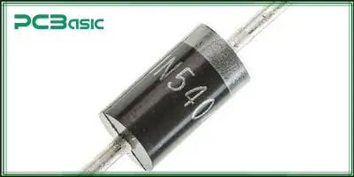
The rectifier diode is the most widely used PCB diode in power circuits, which is used to convert alternating current (AC) to direct current (DC) and only allows current to flow in one direction. Common models include: 1N4001 and 1N5408, which are often used in bridge rectification, power input terminals and other circuits. And it can withstand relatively high voltages and currents.
2. Voltage stabilizing diode
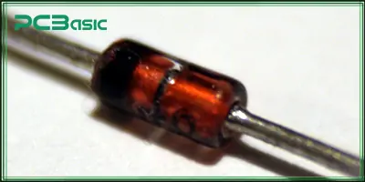
A zener diode is designed to conduct stably when the reverse breakdown voltage is reached, thereby maintaining a constant voltage value. This type of diode is widely used in voltage stabilizing circuits and overvoltage protection circuits, serving as a voltage reference source, voltage clamping, and low-voltage logic protection. It is commonly seen in small voltage control type PCB circuits.
3. Schottky diode
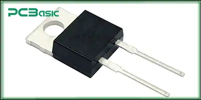
The Schottky diode adopts a metal-semiconductor structure and features an extremely low forward voltage drop (typically 0.2 to 0.4V) and a very fast switching speed. This diode is suitable for applications with high frequency and high power efficiency requirements (such as switching power supplies, DC-DC converters and RF circuits).
4. Light-emitting Diode (LED)

LED emits light when forward-bias and is the most common PCB visual component. It is used for status display, lighting, screen display, etc., and can be provided in a variety of colors and packaging forms. When using light-emitting diodes, current-limiting resistors should be connected in series to prevent overcurrent from damaging the components.
5. Photodiode
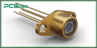
A photodiode is the opposite of an LED. Instead of emitting light, it receives light and converts it into an electric current. It is usually installed in the optical area at the input end of the PCB and is widely used in photoelectric sensors, infrared receivers, optical communication systems, etc.
6. Avalanche diode
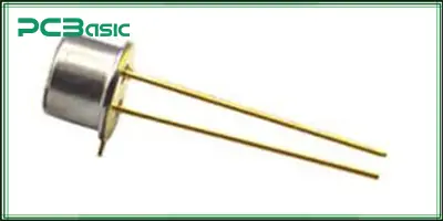
An avalanche diode is specifically designed to deal with sudden high voltages. It looks similar to a voltage stabilizing diode, but its breakdown characteristics are different. It can quickly conduct when there is a high-voltage breakdown, protecting the circuit from the impact of a surge. It is a common overvoltage protection device. It is commonly used in PCBs for automotive electronics, industrial control, etc.
7. PIN, laser, P-N junction diode
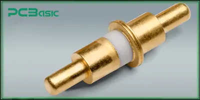
These belong to more specialized diode types and are often used in high-frequency and photoelectric applications. For instance, PIN diodes are commonly used in RF PCBs as switches or attenuators. Laser diodes are used in optical fiber communication or high-brightness light sources. The P-N junction diode is the basic structure that constitutes all common diodes. They are indispensable core components in radio frequency communication, optical fiber systems and laser equipment.
To design circuits, troubleshoot and install components, it is crucial to understand the diode symbols and the diode labels on the PCB. Whether viewing circuit diagrams or soldering diodes on PCBs, understanding their polarity and direction can ensure that the diodes work as expected.
Different types of diodes have corresponding diode symbols in circuit diagrams.
|
Diode Type |
Symbol |
Description |
|
Rectifier Diode |
→ — |
The most common PCB diode, used for current rectification |
|
Zener Diode |
→ —┤ |
Conducts in reverse breakdown; used for voltage regulation |
|
Light Emitting Diode (LED) |
→ —► |
Emits light when forward-bias; commonly used as indicators |
|
Schottky Diode |
→ —S |
Features low forward voltage drop and high-speed switching capability |
These diode symbols can visually represent the direction of current: that is, from the anode (positive pole) to the cathode (negative pole).
So how to identify the polarity of a diode?
Most diodes have a distinct stripe on their bodies, which is used to mark the cathode. The opposite end of the stripes is the anode. It usually corresponds to the following features on the PCB:
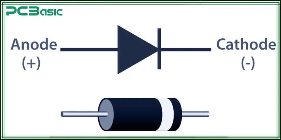
The white stripes on the silk-screen printing
The lines or notches on the solder pads
The arrow direction on the PCB graphic is used to indicate the diode orientation on the PCB.
Whether the diode orientation on PCB is correct or not directly determines whether the circuit can work normally. If installed in reverse, it may cause a short circuit, failure to conduct electricity or burnout. So, how can we identify the direction of a diode?
The methods for identifying the "diode direction" include:
Check the cathode strip on the device body (usually a silver or white ring)
Consult the PCB silk-screen printing or packaging drawings
If it is an SMD package, the polarity can be determined by observing the size and shape of the solder pad
When installing, we should always check the polarity of the PCB diode to avoid circuit failure caused by incorrect direction.
When choosing the appropriate diode for a PCB, it is necessary to comprehensively consider the application requirements and actual conditions. First of all, the purpose needs to be clarified - is the diode used for protection, switch control, rectification, or light emission display? Different uses correspond to different types of diodes, so the application of diodes should be well considered. Secondly, check key electrical parameters such as maximum reverse withstand voltage, current capacity, forward voltage drop and recovery time, etc. Ensure that the selected diode can meet the working requirements of the circuit.
If it is in a high-current or high-speed switching scenario, heat dissipation and power consumption management must also be taken into consideration. At the same time, it is necessary to match the package type well: surface mount diodes (SMD) are suitable for automated mounting in compact spaces, while through-hole diodes are convenient for later maintenance and replacement. Finally, cost and availability cannot be ignored either. Choosing a PCB diode with high cost performance and stable supply is a crucial step to ensure the overall circuit performance and reliability.
Although diodes are small, they are indispensable in PCB design. They undertake multiple tasks such as power rectification, reverse protection, logic control and status indication. To ensure the efficient and stable operation of the circuit, you need to be familiar with different diode types, correctly identify diode symbols and polarity marks, master how to test a diode on a PCB, and ensure that the diode orientation on the PCB during installation is accurate. If you can master these basic skills, then you will surely be able to design more reliable and professional electronic products.
 About PCBasic
Time is money in your projects – and PCBasic gets it. PCBasic is a PCB assembly company that delivers fast, flawless results every time. Our comprehensive PCB assembly services include expert engineering support at every step, ensuring top quality in every board. As a leading PCB assembly manufacturer, we provide a one-stop solution that streamlines your supply chain. Partner with our advanced PCB prototype factory for quick turnarounds and superior results you can trust.

Assembly Enquiry
Instant Quote
Phone contact

+86-755-27218592
In addition, we've prepared a Help Center. We recommend checking it before reaching out, as your question and its answer may already be clearly explained there.
Wechat Support

In addition, we've prepared a Help Center. We recommend checking it before reaching out, as your question and its answer may already be clearly explained there.
WhatsApp Support

In addition, we've prepared a Help Center. We recommend checking it before reaching out, as your question and its answer may already be clearly explained there.
