Global high-mix volume high-speed PCBA manufacturer
9:00 -18:00, Mon. - Fri. (GMT+8)
9:00 -12:00, Sat. (GMT+8)
(Except Chinese public holidays)
Global high-mix volume high-speed PCBA manufacturer
9:00 -18:00, Mon. - Fri. (GMT+8)
9:00 -12:00, Sat. (GMT+8)
(Except Chinese public holidays)
HomePage > Blog > Knowledge Base > Half-Wave Rectifier: Definition, Working, Circuit, Formula, and Applications
In modern electronic technology, most devices require direct current (DC) to operate, while the mains electricity we use daily is alternating current (AC). Rectification is the process of converting alternating current into direct current. Among the various types of rectifiers, the half-wave rectifier is the simplest and most fundamental. It only requires a diode, a load resistor, and sometimes a transformer to convert alternating current into pulsating DC output.
In this article, we will systematically introduce the half-wave rectifier - including its working principle, circuit design, and common mathematical formulas. We will also introduce the standardized half-wave rectifier symbol and explain how these basic circuits lay the foundation for more complex power supply designs. Finally, we will compare it with the full-wave rectifier to explain why different types of rectifiers should be chosen in different scenarios.
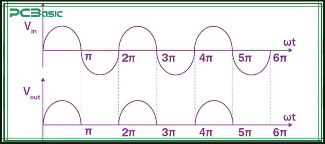
The half-wave rectifier is one of the simplest rectifier circuits. Its working principle is to allow one half-cycle of the alternating current (AC) waveform to pass through while blocking the other half-cycle. Just one PN junction diode, along with a load resistor, and sometimes a transformer for isolation or voltage regulation, can convert sinusoidal alternating current into pulsating DC voltage.
The output current of this kind of circuit is unidirectional, but it is not smooth; instead, it is a series of pulses. Therefore, a filter is usually needed to obtain a more stable direct current. Compared with the full-wave rectifier, its efficiency is much lower because half of the waveform of the alternating current is wasted. But precisely because of its very simple structure, it can often be seen in textbooks, laboratory experiments and some rapid prototyping circuits. It can be said that half-wave rectifiers are the first step to understanding the principle of rectification and further learning the types of rectifiers, especially full-wave rectifiers.
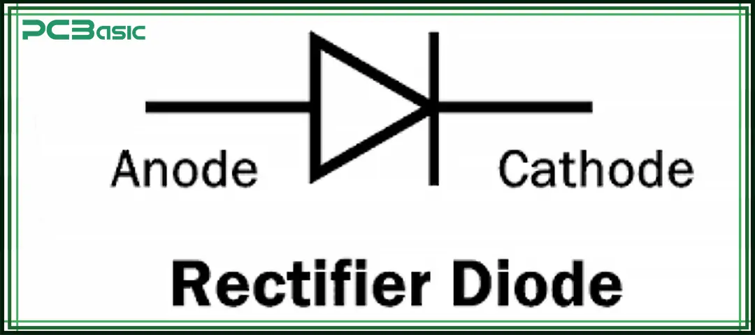
In a circuit diagram, the symbol for a rectifier is the diode symbol, which consists of a triangle and a vertical line. The triangle indicates the direction of the current, from the anode to the cathode, and the vertical line represents the cathode. This is the standard symbol for a diode/rectifier. It should be noted that the symbol with an arrow is generally used for transistors or photodiodes, not for ordinary rectifier diodes.
When drawing a half-wave rectifier circuit, in half-wave rectification, the anode of the diode is connected to the AC power supply and the cathode to the load, making it conduct only in the positive half-cycle. In negative half-wave rectification, the direction of the diode is reversed, making it conduct only in the negative half-cycle. In CAD software or circuit diagrams, we can directly place the standard rectifier symbol (diode symbol) and then adjust the direction as needed. For a more intuitive explanation, you can refer to the half-wave rectifier diagram. In practical applications, there are also different types of rectifiers, such as a full-wave rectifier, which can be selected according to the requirements.
A basic half-wave rectifier circuit consists of the following parts:
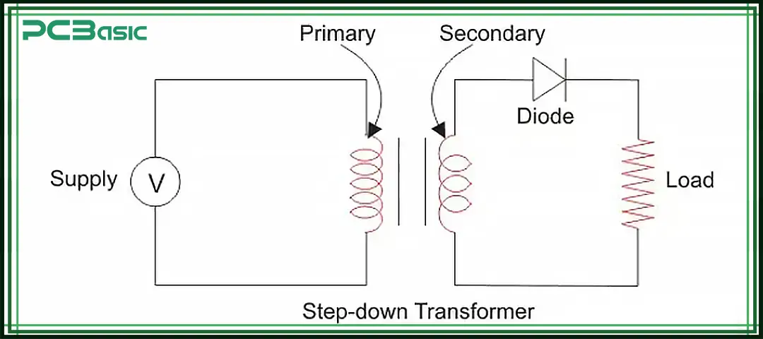
• A transformer (optional but common, used for step-down to ensure safety and voltage adjustment)
• A diode (the rectifier symbol in the circuit diagram)
• A resistive load (RL)
In a half-wave rectifier circuit, alternating current first passes through the secondary winding of the transformer and then goes to the diode and the load resistor (RL). When the input voltage is in the positive half cycle, the diode is in the forward bias state, which is equivalent to a closed switch. The current can flow through the RL, and the output will obtain a positive voltage. During the negative half cycle, the diode is in the reverse bias state, which is equivalent to an open switch. The current is blocked, so the output is zero. This is the basic working principle shown by any half-wave rectifier diagram.
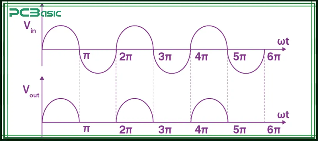
The input sine wave (Vin) will alternate between the positive half cycle and the negative half cycle. After being processed by the half-wave rectifier, the output voltage (Vout) retains only the pulses in a single direction. For example, in a positive half-wave rectifier, the output is only the peak of the positive half-cycle.
In an ideal half-wave rectifier diagram, you will see:
• Vin: A complete sine wave.
• Vout: A series of half-sine shaped pulses that occur once in each input cycle.
If the direction of the diode is reversed, a negative half-wave rectifier can be obtained. In this case, the output shown in the circuit diagram is a pulse in the negative direction, which is very useful when a negative power supply reference is required.

Time is money in your projects – and PCBasic gets it. PCBasic is a PCB assembly company that delivers fast, flawless results every time. Our comprehensive PCB assembly services include expert engineering support at every step, ensuring top quality in every board. As a leading PCB assembly manufacturer, we provide a one-stop solution that streamlines your supply chain. Partner with our advanced PCB prototype factory for quick turnarounds and superior results you can trust.
These classic formulas are derived under the assumptions of an ideal diode and a resistive road, and thus can be used to quantitatively predict the performance of half-wave rectifiers. If the peak value of the input voltage is Vm (from the secondary side of the transformer), then the peak current is Im = Vm/RL.
• Average (DC) output voltage:
• Average (DC) load current:
• RMS load current:
• RMS output voltage:
• Form factor (RMS/average):
• Ripple factor γ (AC content relative to DC):
• Rectifier efficiency η (DC output power / AC input power):
(for an ideal half-wave rectifier)
• Peak Inverse Voltage (PIV) for the diode:
(Ensure the diode’s reverse-voltage rating safely exceeds Vm with margin.)
These formulas are very practical when learning and using half-wave rectifier circuits. They can help us understand the half-wave rectifier diagram and select the appropriate Diode. Or provide evidence when comparing different rectifier types, such as a full-wave rectifier and a half-wave rectifier.
Although the half-wave rectifier is not very efficient, it still has many practical uses. It is often used in signal demodulation, such as in the detector or peak detector circuits of AM radios. It can also be used for pulse generation and peak detection. In some situations where power requirements are not high, it can still be applied in low-power DC chargers, especially in some traditional or teaching experimental circuits.
Furthermore, half-wave rectifier circuits also frequently appear in bench Education and training because they can help beginners understand the basic principles of different types of rectifiers. When the design only requires a simple polarity selection, the half-wave rectifier is often the most convenient and direct choice.

A full-wave rectifier is also a circuit that converts alternating current (AC) into direct current (DC). Its characteristic is that it can simultaneously utilize the positive half cycle and negative half cycle of the AC waveform and convert both of them into a pulsating DC output. In contrast, the half-wave rectifier only utilizes half of the alternating current waveform, so it is less efficient and the output voltage is not as stable.
It is precisely because the full-wave rectifier can handle two half-cycles of alternating current that it can achieve a higher average DC voltage and a lower ripple factor compared to the half-wave rectifier, and the transformer utilization rate is also better.
Understanding where a half-wave rectifier shines (and where it doesn't) is easiest when contrasted with a full-wave rectifier:
|
Feature |
Half-wave Rectifier |
Full-wave Rectifier |
|
Diodes |
1 |
2 (center-tap) or 4 (bridge types of rectifiers) |
|
Utilization of the AC Cycle |
Only one half-cycle |
Both half-cycles |
|
Average DC Output |
0.318 Vm |
0.637 Vm |
|
Ripple Factor (no filter) |
~ 1.21 |
~ 0.48 |
|
Efficiency (ideal) |
~ 40.6% |
~ 81% (theoretical upper bound idealized comparison) |
|
Transformer Utilization |
Poor |
Better |
|
Output Smoothness |
Lower |
Higher |
|
Common Use |
Low-power, demo, detectors |
Power supplies, chargers, and regulated DC front-ends |
The half-wave rectifier is the most common introductory circuit for learning rectification. It only requires a few components to help understand the basic principle of rectification. By observing the half-wave rectifier circuit, using the rectifier symbol correctly, and combining with the half-wave rectifier diagram, we can correlate the variation of voltage over time with formulas, such as average, RMS, ripple, efficiency, and maximum reverse voltage (PIV).
If a more stable direct current is needed, a full-wave rectifier or a bridge rectifier is usually chosen because they have a higher output voltage and smaller ripple. However, half-wave rectifiers still have their own uses: they are low in cost, have a simple and intuitive structure, and are very suitable for use in circuits such as demodulation and peak detection. They are also the basic tools for power electronics engineers to build an intuitive understanding.
1) What is a half-wave rectifier?
A half-wave rectifier is a one-diode half-wave rectifier circuit that passes one half of the AC cycle and blocks the other, producing a pulsating DC across a load. It’s the simplest member of the types of rectifiers and a baseline for understanding the full-wave rectifier.
2) Where is a half-wave rectifier used?
Use a half-wave rectifier for low-power tasks and signal processing—AM demodulation, peak detection, and educational demos. For power supplies, designers typically move to a full-wave rectifier (bridge or center-tapped) within the broader types of rectifiers.
3) Why is a capacitor used with a half-wave rectifier?
The output of a half-wave rectifier circuit is pulsating DC with a large ripple. A capacitor across the load charges on conduction peaks and discharges between peaks, smoothing the waveform. This classic "reservoir" action reduces ripple and is often depicted in a half-wave rectifier diagram.
4) What is the efficiency of a half-wave rectifier?
In ideal analysis, the half-wave rectifier peaks at about 40.6% efficiency (DC output power divided by AC input power). A full-wave rectifier dramatically improves utilization, which is why it dominates practical types of rectifiers for power supplies.
5) Which is better: a half-wave or a full-wave rectifier?
For nearly all supply applications, the full-wave rectifier is better—more DC output, less ripple, better transformer utilization. The half-wave rectifier wins when you need absolute simplicity or you're building detector/peak circuits. In the family of types of rectifiers, choose based on performance needs and component budget.

Assembly Enquiry
Instant Quote
Phone contact

+86-755-27218592
In addition, we've prepared a Help Center. We recommend checking it before reaching out, as your question and its answer may already be clearly explained there.
Wechat Support

In addition, we've prepared a Help Center. We recommend checking it before reaching out, as your question and its answer may already be clearly explained there.
WhatsApp Support

In addition, we've prepared a Help Center. We recommend checking it before reaching out, as your question and its answer may already be clearly explained there.
