Global high-mix volume high-speed PCBA manufacturer
9:00 -18:00, Mon. - Fri. (GMT+8)
9:00 -12:00, Sat. (GMT+8)
(Except Chinese public holidays)
Global high-mix volume high-speed PCBA manufacturer
9:00 -18:00, Mon. - Fri. (GMT+8)
9:00 -12:00, Sat. (GMT+8)
(Except Chinese public holidays)
HomePage > Blog > Knowledge Base > Types of Electrical Connectors: A Complete Guide for PCB Design and Assembly
Today's smartphones, medical monitors, factory robots, and countless other gadgets depend on tight, reliable contacts to do their jobs. Behind that reliability lurks a small yet critical item: the electrical connector. As products shrink, operate at higher speeds, and handle more power, picking the right connector has grown into a key call for PCB design and assembly.
Because the market offers everything from wire-to-board, board-to-board, and USB-C plugs to RF sockets, engineers must know how each style functions, where it fits, and how to match it to the job's real requirements. This guide explains different types of automotive electrical connectors, describes their roles in the PCB world, and offers practical tips for choosing different types of electrical wire connectors that deliver long-term performance and toughness.
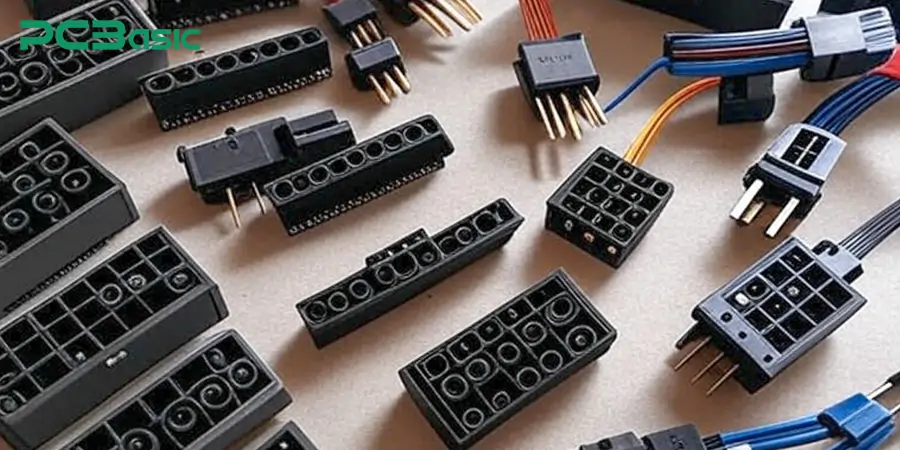
Electrical connectors act like doorways that link circuits, modules, or entire pieces of equipment, letting currents and signals flow smoothly. Without them, modular design, quick maintenance, and future upgrades would be nearly impossible.
At its core, a connector is the handshake that keeps all the parts of a system talking to one another.
Take a computer motherboard as an example - it uses many PCB connector styles to link memory, graphics cards, storage drives, and input/output ports.
If those inter-module links break, the independent boards lose the ability to function as a cohesive unit.
How Connector Selection Impacts PCB Layout and Assembly?
The very first design decision is the connector because that part drives the rest of the layout. Its mounting location, orientation, and footprint determine trace routing, affect board real estate, and form the mechanical backbone. In cramped enclosures or at defined service points, designers often specify right-angle headers or top-entry sockets.
Ignoring these factors can force expensive re-spins, delay assembly, and create headaches like increased noise or unreliable joints.
In fast digital buses or sensitive analog paths, the wrong connector adds reflections, cross-talk, or hiss that downstream filtering cannot erase. Meanwhile, automotive or outdoor connectors must seal tightly against moisture, withstand vibration, and resist thermal aging. In mission-critical equipment, a weak joint can crash the entire system.
Thus, following electrical connector types chart, specifying high-grade materials-such as gold-plated contacts-and integrating robust locking features are essential for dependable, quiet connections.
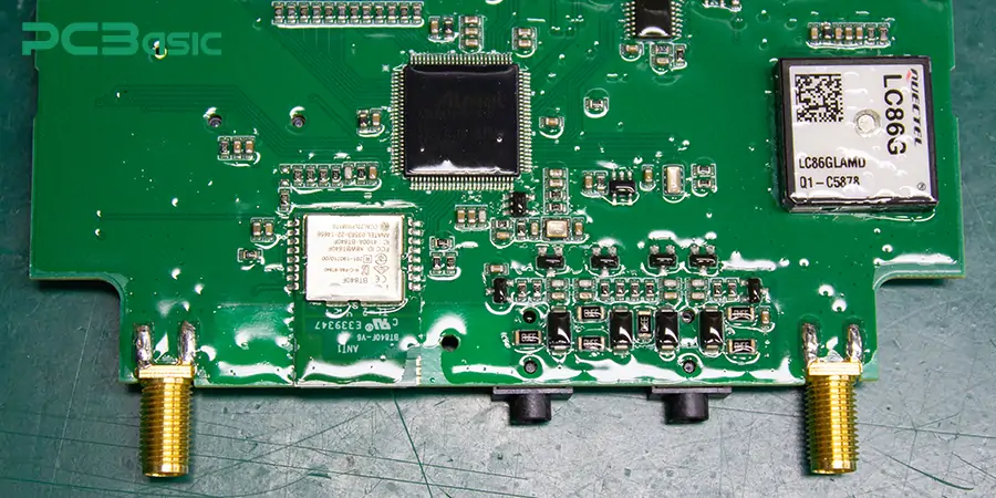
When engineers set out to craft a dependable, high-performing printed circuit board, picking the correct electrical connectors is as important as deciding on the right ICs, capacitors, or resistors.
Connectors ultimately control how a circuit board talks to outside devices, feeds on power, or links with other boards. Choose the wrong one, and the entire gadget- whether a pocket phone or a rugged factory controller stumble or quit altogether.
The connector market offers different types of automotive electrical connectors for PCB work. Each type is crafted for its own blend of mechanical and electrical needs-voltage, current, space, signal quality, and any physical stresses the board will meet. Some parts carry high-speed data, others pass heavy power, and a few tie flexible cables inside cramped housings.
The outline below reviews different types of electrical connectors found in today's PCB projects, explaining their traits, ideal uses, and chief advantages.
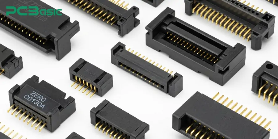
Board-to-board connector types nest two printed circuit boards together, either in a vertical stack or side by side.
They come in three basic orientations-vertical, right-angle, and mezzanine. Because it saves space, designers prefer this arrangement in compact products like laptops, tablets, and embedded modules.
Benefits:
· Rugged, streamlined assembly
· Fast, low-latency signals
· Less cabling and shorter build time
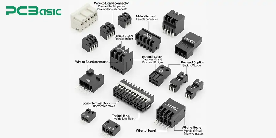
Wire-to-board connectors are among the most widely used electrical links. They join stranded or solid wires directly to a PCB, often featuring latches that lock the connection and guard against unintentional release.
You can find them everywhere-from dishwashers and car consoles to robotic arms on the factory floor.
They include several common termination styles:
· crimp terminals
· IDC (insulation displacement connectors)
· screw terminal blocks
These styles let technicians swap wires on-site and work with different gauges and insulation without special tools.
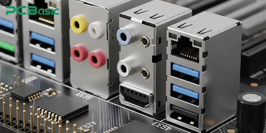
Input/output connectors bridge a circuit board to outside hardware or networks. Familiar standards in this family include:
· USB-C, a versatile data and power link
· HDMI for high-definition video and audio
· Ethernet, carrying network packets
· audio jacks and Display Port
Many modern I/O plugs bundle data, video, and power in cable connector types. USB-C has emerged as the go-to choice for laptops, phones, and peripherals.
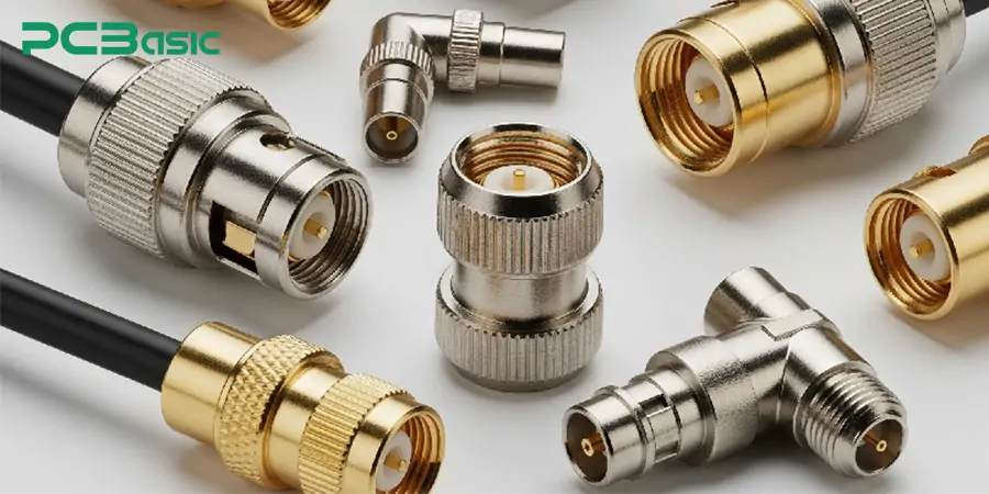
Radio-frequency and coaxial connectors are vital for broadcast and cable systems. Their design keeps losses low and shields sensitive circuits from outside noise, which is why they show up in every communication box.
Screw-mount or snap-on types such as SMA, BNC, and MCX carry high-frequency signals in radios, Wi-Fi cards, GPS modules, and antenna boards.
Benefits:
· Negligible insertion loss
· Faraday shielded against EMI
· stable gain at gigahertz frequencies
These types of electrical wire connectors form the backbone of modern commercial equipment, appearing on both satellite payloads and base station radios.
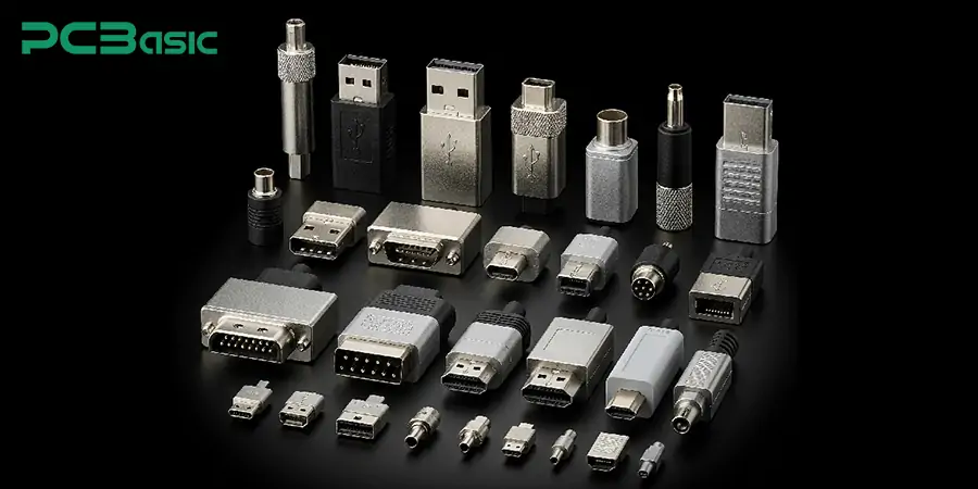
Power types of connectors channel electrical current, ensuring devices continue to function properly.
Industrial-grade connectors feature more rigid casings, beefier pins, and voltage-current specs that align with factory rules.
Common examples
· Barrel connectors
· are those familiar DC jacks
· ATX power plugs found inside PCs
· Screw terminal blocks.
You’ll also see these parts inside LED strips, electric vehicle powertrains, and factory control panels.
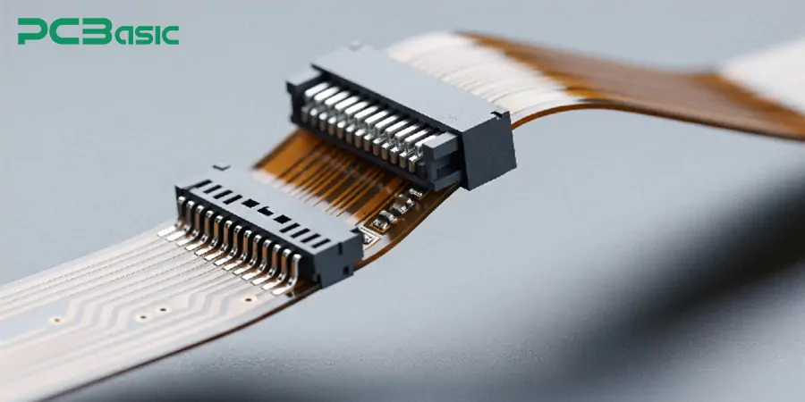
Flexible printed-circuit mates-link bendable flat cables to solid motherboard pads. Their slim profile is particularly important in phones, cameras, and foldable gadgets that leave little room for extras.
Features
· Paper-thin design that bends without cracking
· Push-to-lock, pull-to-release tabs
· Surface-mount or zero-insertion-force (ZIF) sets.
· They trim weight and volume yet still provide dependable data paths.
Electrical Connector Types Chart
|
Connector Type |
Key Features |
Typical Applications |
|
Board-to-Board |
Vertical, right-angle, mezzanine options; compact, fast signals |
Laptops, tablets, embedded modules |
|
Wire-to-Board |
Latching, field-serviceable, works with various wire gauges |
Appliances, vehicles, industrial equipment |
|
I/O Connectors |
Standardized protocols, combine power/data/video |
External interfaces: data, video, audio, network |
|
RF/Coaxial |
Low loss, EMI shielded, high-frequency stability |
Communication, wireless, RF systems |
|
Power Connectors |
High current handling, rugged pins, industrial-grade |
Power supply, EV, LED lighting, control panels |
|
FPC/FFC |
Ultra-thin, flexible, space-saving, ZIF-compatible |
Mobile phones, cameras, foldables |
Choosing the right connector for a circuit board means weighing many technical and mechanical details.
Current and Voltage Rating
First, check that the part can handle the required voltage and current. Devices that operate above their rated capacity can overheat, bond together, or even spark nearby plastic. That rule is especially true for power connectors on motor drives, inverters, or big supplies.
Signal Speed and Frequency
In fast digital or radio-frequency circuits, minor mismatches can sour data. Reflections, sudden impedance steps, and stray coupling chip away at clarity.
Select electrical types of wire connectors types that match line impedance, offer low return loss, and provide adequate shielding at high frequencies.
Mechanical Durability (Insertion Cycles)
In many projects, connectors must be plugged and unplugged dozens, sometimes hundreds, of times. For these duties, choose parts rated for thousands of cycles with no noticeable wear. Automotive connectors often fit the bill, as they survive regular maintenance in tough conditions.
Space and Height Constraints
Today's designs leave scant room for bulky hardware. When a board's height or width is limited, pick low-profile or compact connectors. Also, check pin pitch; tighter spacing allows more parts but can complicate assembly.
Soldering vs. Press-Fit vs. Surface Mount
Next, settle on the mounting technique-soldered, press-fit, or surface mount. Each method carries different costs, dependability, and repair needs. Choosing the proper technique for the task eases both production and service.
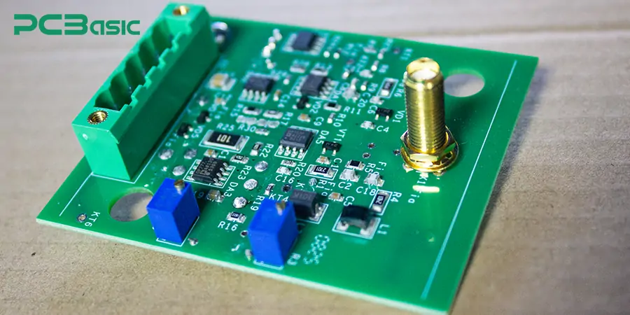
Surface Mount Technology (SMT) is commonly used in high-volume runs and space-constrained products because it allows components to lie flat against the board. Through-hole headers and sockets, by contrast, anchor solidly through drilled holes, creating joints that resist bending and pulling. Press-fit pins, frequently employed in automotive and industrial assemblies, bite securely into plated holes without solder. This feature earns them a reputation as the preferred connector for printed circuits exposed to repeated vibration and wide thermal swings.
Whatever connection style is selected, ripples straight to the shop floor, shaping setup jigs, soldering routines, defect rates, and the bill for raw materials.
Cost vs. Performance Trade-offs
High-end connectors can offer gold-plated contacts, oil-tight enclosures, and low-resistance geometries. Such refinements extend longevity and signal accuracy, yet they push per-unit costs into premium territory.
Today's smartphones usually aim for the leanest parts list. In contrast, aerospace, automotive, and medical designs expect every interface to survive extreme stress.
The connector you select does far more than conduct current; it guides the whole board assembly, from pad layout to the final inspection station.
Impact on PCB Fabrication: Pad Design, Footprint, Hole Sizes
Footprint dimensions, hole diameter, and copper plating must align with each connector to prevent brittle joints, cold solder, or stealth failures down the line. Surface-mount devices need flat pads that receive paste smoothly and melt uniformly. Through-hole components require drilled pads, plated vias, and solder masks that stop molten alloy from wick-ing upward during wave solder. Flexible cables often crave low-profile pads and wide keep-outs to protect slender traces from bending and shear. Datasheets list every critical measurement, so engineers should always check them rather than relying on guesswork.
Assembly Considerations: SMT vs. Through-Hole Connectors
The flat-mount cable plugs are picked up under a vacuum, dropped onto the pad in seconds, and passed straight into a reflow oven that fuses the solder with no human handling. Through-hole connectors, in contrast, are usually pushed into place by an operator or pressed in by a small robot before being secured with a wave solder or touched up by a hand iron.
When a single board carries both SMD and through-hole parts, the line has to run a dual-reflow cycle, which raises setup time, rework chances, and overall build complexity.
Testing and Inspection During Assembly (AOI, ICT)
Because the behavior of the whole device often rides on the strength of its connectors, quality oversight is mandatory. Staggered, lifted, or cold joints can trigger field failures that cost money and can even put people at risk. For that reason, PCB shops rely on:
- AOI (Automated Optical Inspection) to catch misplacements and bad joints.
- ICT (In-Circuit Testing) to confirm that every trace is live and free of shorts.
- Functional tests that simulate real operation.
These layers of verification matter even more for automotive connections, which must clear ISO 16750, IPC-A-610, and other exacting standards.

Whether your project is still a prototype or already climbing into large runs, working with a trusted partner like PCBasic makes sure that each connector lands where it should and stays supported from the first sketch to the final board.
Why Choose PCBasic?
· Wide Connector Compatibility: Deep experience with USB-C, standard PCB headers, automotive terminals, and many other formats.
· Custom PCB Layout Support: Help create precise footprints and pad patterns for unusual wire-to-board components.
· End-to-End Service: Schematic check, parts buying, and complete assembly, all using cable parts that have been thoroughly screened.
· Robust Testing: Each board goes through in-house AOI, X-ray, and continuity tests before it ships.
Choosing PCBasic cuts defects lifts quality, and quickens time to market while tapping into decades of connector know-how.
In electronic gear, even the smallest part can change everything. Choosing the right connector for a PCB can move a project toward victory or throw it off course. Whether carrying power, data, or RF, each job calls for a connector that matches its purpose. From wire-to-board and board-to-board devices to flexible FPC and general I/O styles, every category offers distinct benefits.
In mission-critical environments such as automotive electronics or industrial control systems, only rugged, high-performance connectors should be deployed. Current rating, installation space, mechanical durability, and the desired mating method all dictate the final selection. Use a cross-reference chart to compare types and finalize your choices early, avoiding costly redesigns later. Once manufacturing starts, an experienced partner like PCBasic installs inspects and certifies each connector to ensure it operates reliably in service.
 About PCBasic
Time is money in your projects – and PCBasic gets it. PCBasic is a PCB assembly company that delivers fast, flawless results every time. Our comprehensive PCB assembly services include expert engineering support at every step, ensuring top quality in every board. As a leading PCB assembly manufacturer, we provide a one-stop solution that streamlines your supply chain. Partner with our advanced PCB prototype factory for quick turnarounds and superior results you can trust.

Assembly Enquiry
Instant Quote
Phone contact

+86-755-27218592
In addition, we've prepared a Help Center. We recommend checking it before reaching out, as your question and its answer may already be clearly explained there.
Wechat Support

In addition, we've prepared a Help Center. We recommend checking it before reaching out, as your question and its answer may already be clearly explained there.
WhatsApp Support

In addition, we've prepared a Help Center. We recommend checking it before reaching out, as your question and its answer may already be clearly explained there.
