Global high-mix volume high-speed PCBA manufacturer
9:00 -18:00, Mon. - Fri. (GMT+8)
9:00 -12:00, Sat. (GMT+8)
(Except Chinese public holidays)
Global high-mix volume high-speed PCBA manufacturer
9:00 -18:00, Mon. - Fri. (GMT+8)
9:00 -12:00, Sat. (GMT+8)
(Except Chinese public holidays)
HomePage > Blog > Knowledge Base > Distance Relay: Types, Diagrams, and Working Principles
To maintain stability and ensure equipment is not damaged, modern power systems require the reliable and selective isolation of faults. One of the most potent and popular protective devices used on transmission lines is the distance relay.
Unlike traditional overcurrent relays which trip in any condition resulting in excessive current, offering no speed or accuracy, distance relays measure the impedance between the relay and the fault point, thus giving both speed and accuracy to the protection scheme.

Distance relay protection has been defined as a part of relay protection in power systems that detects and isolates faults based on the distance between the relay and fault points. Unlike overcurrent relays, which only respond to the magnitude of current, a distance relay measures the impedance of the line, which varies according to the distance to the fault. If the measured impedance falls below a predefined value given for a specific zone, it indicates the fault, which normally triggers the relay's trip action.
The popular term "impedance relay" has been used as a synonym for distance relay since the fundamental idea in working is based on measuring the line impedances. Hence, the scope of this type of relay is suited to the protection of the transmission line where swift operation and accuracy in locating the fault are imperative.
These devices are installed at high-voltage substations of distance protective relays designed to protect long lines against the effects of short circuits, line-ground faults, and other abnormal conditions.
So, if you are inquiring about distance relays, they are intelligent fault detection devices that enhance reliability and selectivity in modern power system protection.
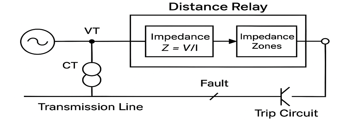
A diagram of a distance relay describes how the working of the relay is based on the impedance measurement within a power system. The general layout shows the relay unit, voltage and current transformers (VT and CT), and a transmission line.
A basic description of a distance relay diagram is as follows:
• CTs and VTs: Make measurements of line current and voltage.
• Relay Unit: It computes the impedance Z=V / I
• Impedance Zones: Defined areas that determine whether a fault is on the trip range.
• Trip Circuit: Engages when the fault in question falls within a given impedance zone.


Distance relays are the lifeline of high-voltage transmission lines. They are intended especially for the protection of high-voltage transmission lines. Because faults can be detected according to line impedance rather than currents or voltage values alone, distance relays serve excellent selective and reliable protection.
The most common use of distance protection relays is safeguarding overhead and underground transmission lines from faults such as line-to-ground, line-to-line, or three-phase short circuits.
Distance relays serve as backup protection in case differential or overcurrent protection schemes fail. They ensure the isolation of faulty components in complex grid systems.
Distance relays provide zone-based protection for fast and effective isolation of faults in feeder lines spanning long distances in the countryside.
These relays act in several zones with certain time delay settings. This zoning operates in sophisticated systems requiring an overlap of protection and backup functions.
As our power grids become increasingly interrelated, impedance relays will be increasingly important for maintaining stability in a grid by detecting faulted lines and isolating them to prevent chain outages.
In high voltage direct current and extra high voltage networks, fast-acting distances relay for distance-sensitive protection will operate dependably in any required situation.
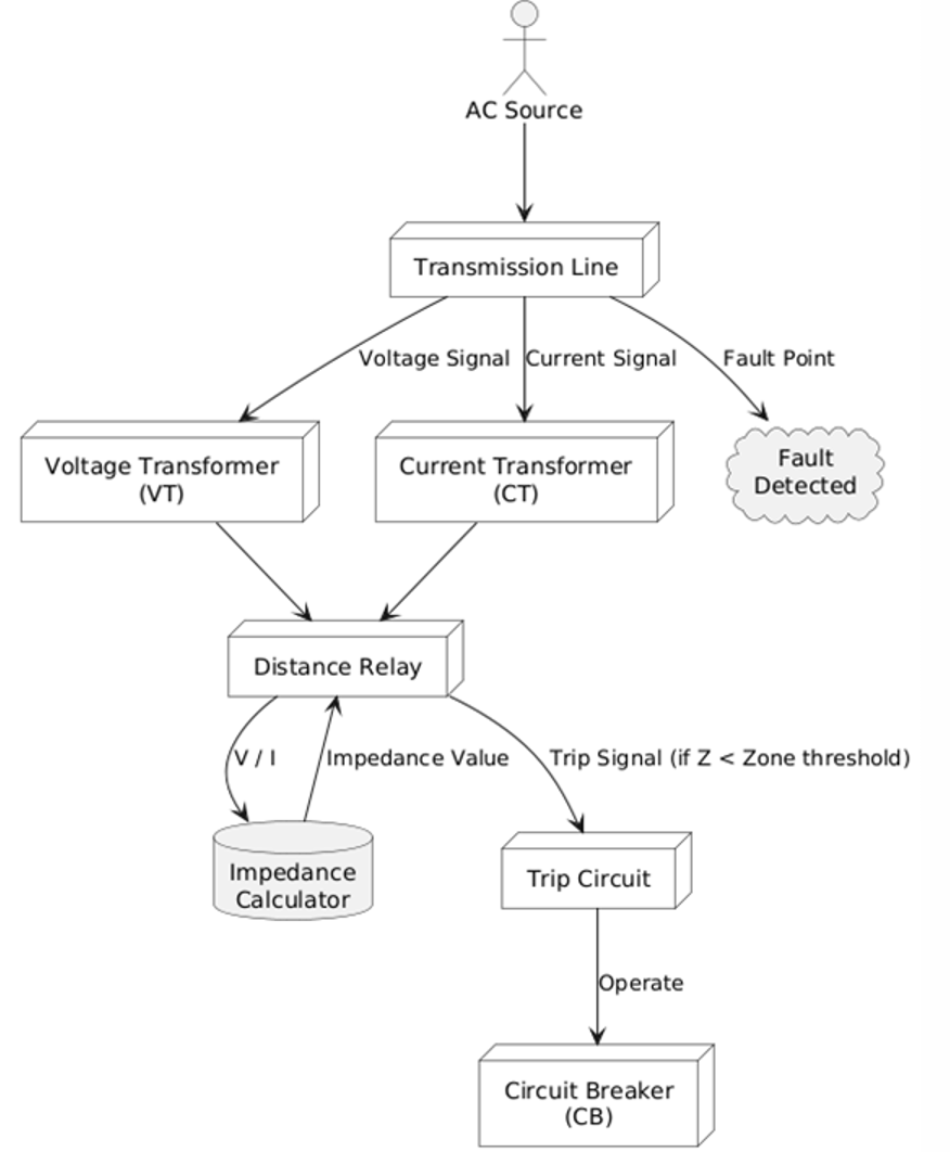
The distance relay functions based on the measurement of the impedance (Z) from the location of the relay to that of the fault on the transmission line. Since the impedance is directly proportional to the distance along the length of the line, this means that the relay is able to very effectively estimate how far away a given fault is from itself.
When the calculated impedance falls below a predefined threshold count, the relay determines that a fault exists within its protection zone and sends a trip signal to isolate the faulty section.
Input Signals
The distance relay receives voltage and current inputs from voltage transformers (VTs) and current transformers (CTs) installed on the line.
Impedance Calculation
With the impedance being calculated by the formula, Z = V / I, where V is voltage and I is current, the relay is continuously calculating the impedance of the line under protection.
Zone Comparisons
The impedance measured is compared to the set values, coinciding with the zone under comparison (Zone 1, Zone 2, Zone 3). Each zone would have a certain range of distances associated with its working time.
Trip Recommendations
If the impedance falls within the range of a zone, the distance protection relay issues a trip signal:
• Zone 1: Instantaneous tripping for close-in faults.
• Zone 2 & 3: Time-delayed tripping for remote faults or backup protection.
Directional element (if needed):
Some relays include a directional element such as the MHO relay to check that the fault is in the forward direction; this is to avoid any misoperation.

Time is money in your projects – and PCBasic gets it. PCBasic is a PCB assembly company that delivers fast, flawless results every time. Our comprehensive PCB assembly services include expert engineering support at every step, ensuring top quality in every board. As a leading PCB assembly manufacturer, we provide a one-stop solution that streamlines your supply chain. Partner with our advanced PCB prototype factory for quick turnarounds and superior results you can trust.
Distance relays can be classified according to the property of the relay used to establish the presence and location of the fault. Each type behaves in its own way, depending on impedance, reactance, admittance, or the time factor in the operation. The distance relay types hold significance in determining the selection of a protection scheme for various parts of the power system.
An impedance relay is initiated when the impedance measured between the relay position and the fault is below an established value. This is one of the simplest types of distance protection relays, usually characterized as a circular relay in the R-X (Resistance-Reactive) plane.
Impedance relays do not have directional characteristics and can, therefore, not distinguish between forward and reverse faults on their own unless supplemented with a directional element.
The reactance relay operates solely on the reactance part of impedance. This makes it particularly useful for the detection of high-resistance faults where the resistive component is important. Its operating characteristic is a straight line parallel to the R-axis in the impedance plane.
Reactance relays are commonly considered for ground-fault protection on short lines, where one might expect the resistive components to interfere with the correct operations of other relays.
It is well-known that the basic working principle of an MHO relay, or admittance relay, is that it develops an operating condition whenever the measured admittance goes above the limit criteria. This will have a directional circular characteristic that passes through the origin in the R-X diagram.
Therefore, this inherently makes it a directional relay and very suitable for long transmission lines and interlinks due to its features necessary for the applications related to fault direction detection. MHO relay is generally used for most modern types of digital distance relay systems.
Definite distance relay trips whenever the measured impedance falls below a certain set value, but without any intentional time delay. So, it is the fastest protection and is mainly applied for Zone 1 (instantaneous) protection, where faults are likely to happen close to the relay location. They offer quite a clear and rigid boundary for tripping decisions and very easy coordination.
Time-distance relays combine impedance-based operation with a time delay element. The farther the fault is from the relay location (i.e., the higher the impedance), the longer the relay takes to operate.
This time grading allows for better coordination with downstream and upstream relays, making it ideal for multi-zone protection schemes.
Distance relays essentially provide numerous advantages on the practical side, being among the most preferred protection devices in high-voltage transmission systems. Such type of relay measures the electrical distance as opposed to current and voltage. Hence, they are very accurate and up to a good level, and reliable under almost any fault condition.
Distance relays isolate only the faulty section of the line, which ensures minimum disruption in the rest of the power system. This selective tripping capability improves system stability and service continuity.
While distance protection relay operates almost instantaneously in Zone 1 for close-in faults, an isolated disconnection takes place and limits damage on equipment.
Multi-Zone distance relays provide an excellent solution for graded protection for short, medium, and long distances. This inherent flexibility allows for very easy coordination with neighboring relays and systems.
Distance relays, unlike overcurrent relays, are not affected directly by load variation or current magnitude. This means response is totally based on impedance and hence assures fault detection regardless of load conditions.
The distance relays are expected to eliminate or reduce complex communication lines between substations, especially when using time-graded protection zones.
Distance relays, with their high accuracy and dependability, are very much suited for protection against EHV and UHV transmission line failures.
Distance relays are incredibly important tools for power system protection that offer utmost precision, speed, and reliability for fault detection based on electrical distance rather than current magnitude alone. They achieve this by calculating the impedance and accurately determining the point of fault and initiating tripping actions to minimize the disturbances in the system and guarantee the safest conditions.
There are different distance relay types include an impedance relay, a reactance relay, an MHO relay and more. Each is suitable for different protection scenarios.
This widespread application in high-voltage transmission networks goes a long way to validate their strong merit for grid stability and operational efficiency. As digital relaying technology continues to evolve, distance protection relays will be instrumental in future-smart grid scenarios.

Assembly Enquiry
Instant Quote
Phone contact

+86-755-27218592
In addition, we've prepared a Help Center. We recommend checking it before reaching out, as your question and its answer may already be clearly explained there.
Wechat Support

In addition, we've prepared a Help Center. We recommend checking it before reaching out, as your question and its answer may already be clearly explained there.
WhatsApp Support

In addition, we've prepared a Help Center. We recommend checking it before reaching out, as your question and its answer may already be clearly explained there.
