Global high-mix volume high-speed PCBA manufacturer
9:00 -18:00, Mon. - Fri. (GMT+8)
9:00 -12:00, Sat. (GMT+8)
(Except Chinese public holidays)
Global high-mix volume high-speed PCBA manufacturer
9:00 -18:00, Mon. - Fri. (GMT+8)
9:00 -12:00, Sat. (GMT+8)
(Except Chinese public holidays)
HomePage > Blog > Knowledge Base > DIP Switches: Types, Diagrams, Applications, and Address Charts
In modern electronics, flexibility, configurability and simplicity are of great importance. The DIP switch precisely combines these three points. It is small in size but can complete important hardware configurations in electronic devices. With DIP switches, manufacturers and users can directly adjust the working mode of the equipment without complicated software or interfaces.
Although some people may think that DIP switches are somewhat outdated, they are still widely used in many industries, especially in industrial automation, embedded systems, test equipment and consumer electronics. Because they are reliable, low-cost and easy to operate, DIP switches are still very common even as technology keeps advancing.
This article will introduce the definition of DIP switches, their working principle, DIP switch diagrams, DIP switch circuit diagrams, different types of DIP switches, and how to use DIP switch address charts to configure devices.
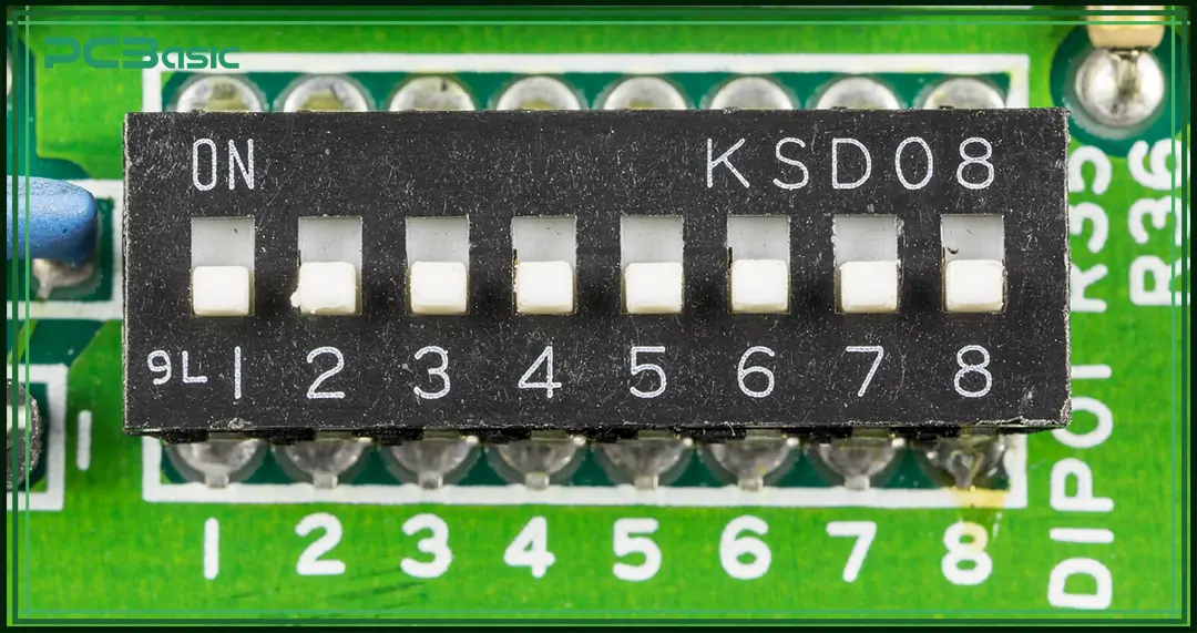
The DIP Switch, whose full name is Dual In-line Package Switch. Its shape is a small rectangular case with two rows of parallel pins at the bottom, and its appearance is similar to a traditional integrated circuit (IC). The DIP switch is composed of multiple small switches, each of which can be individually switched to ON or OFF, that is, to connect or disconnect the circuit. Some models have a third position.
Unlike configuration methods that require software, drivers or interfaces, DIP switches can be quickly changed directly on the hardware. The position of each switch represents a specific setting, which is very suitable for fixed hardware configurations that do not need to be frequently changed.
DIP switches first appeared in the 1970s and were soon widely used in early personal computers, arcade games, communication devices and industrial controllers. They were often used to set parameters such as interrupt request (IRQ), memory address and device addresses in serial communication networks.
Although many systems are now configured with firmware or software, DIP switches remain important in places where hardware control, high stability and long-term reliability are required.
The main function of the DIP switch is to control whether a circuit is open or closed. There are multiple small switches inside it. Each switch has its own contacts and can control the flow of current.
• When the switch is set to "ON", the contacts close, then the circuit is connected, and the current flows smoothly.
• When the switch is set to "OFF", the contacts open, the circuit is disconnected, and the current cannot flow.
Since the DIP switch is of mechanical structure, its state remains unchanged unless the switch is manually changed. Therefore, in many places where long-term stable settings are required, DIP switches are very reliable.
The internal structure of each DIP switch generally includes:
• Contacts: The conductive parts that connect or disconnect the circuit.
• Actuator: The small lever that users move by hand to switch ON or OFF.
• Spring mechanism: Keeps steady pressure on the contacts to prevent loosening.
• Housing: Usually made of heat-resistant plastic to protect the internal structure.
Normally, when the device is powered on and starts up, the microcontroller or logic circuit in the system will automatically read the status of the DIP switch. According to whether each switch is ON or OFF, the logic circuit determines the working mode and functional settings of the equipment.
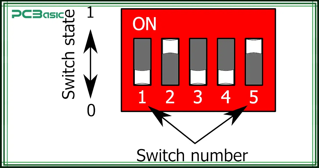
The DIP switch diagram shows the layout and numbering of the switches inside the package. It usually includes:
• The switch positions numbered (for example: 1 to 8, 1 to 10, or 1 to 16).
• An "ON" label that shows which direction is ON.
• Helping users set each switch correctly according to the required settings.
Technicians and engineers often use the DIP switch diagram during hardware installation and setup to make sure the switch direction and settings are correct.
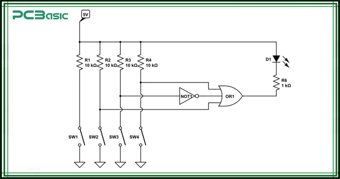
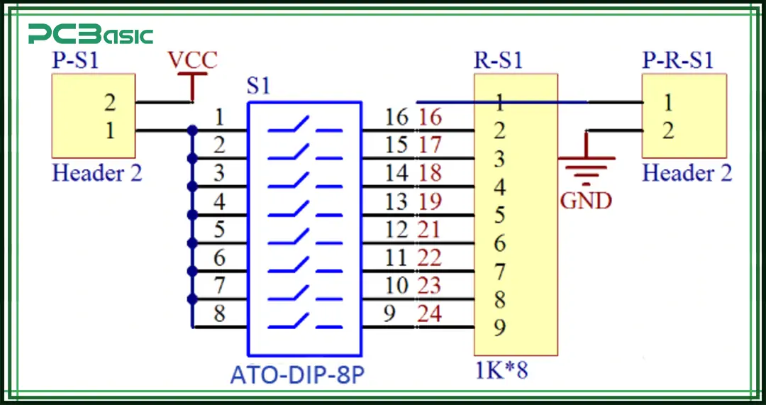
The DIP switch schematic shows how the switches are connected in the circuit. In the schematic:
• Each switch is usually shown as a simple open/close symbol (Single Pole Single Throw, SPST).
• More complex designs may use Single Pole Double Throw (SPDT) symbols.
• The DIP switch schematic helps circuit designers see how the switch positions affect the overall circuit logic.
By reading the DIP switch schematic, designers can make sure the DIP switch is properly connected to digital or analog systems so the circuit works as expected.
 About PCBasic
Time is money in your projects – and PCBasic gets it. PCBasic is a PCB assembly company that delivers fast, flawless results every time. Our comprehensive PCB assembly services include expert engineering support at every step, ensuring top quality in every board. As a leading PCB assembly manufacturer, we provide a one-stop solution that streamlines your supply chain. Partner with our advanced PCB prototype factory for quick turnarounds and superior results you can trust.
Although the basic function of a DIP switch is to turn a circuit on or off, there are different types depending on the application and mounting method.
1. Slide DIP Switch
This is the most common type of DIP switch. The lever slides left-right or up-down to turn the switch on or off. It is usually available in SPST and SPDT models, with two or three positions.
2. Piano DIP Switch
It is named because it looks like piano keys. You press the switch down to change the position. It is good for circuit boards with limited space where sliding is not possible.
3. Rotary DIP Switch
The knob rotates to select different positions. It often has numbers or hexadecimal markings. It is often used for setting addresses or modes, offering many options in a small space.
4. Rocker DIP Switch
This type works like a seesaw. You press one side to switch positions. It is not very common but has a good tactile feel. It is used in some industrial or consumer electronics.
5. Tri-State DIP Switch
This switch has three positions: high, low, and high-impedance. It allows many combinations and is useful for setting addresses and modes in large communication or sensor networks.
6. SPDT DIP Switch
An SPDT DIP switch gives two paths for the current. It switches between two circuits instead of just turning on or off. It is often used in complex logic circuits, signal routing, and testing equipment.
In the use of DIP switches, device addressing is a very important function. To make configuration easier, many devices use a DIP switch address chart.
Each switch position on a DIP switch represents a binary bit:
• ON means 1.
• OFF means 0.
When several switches are combined, they form a binary code. The system uses this code as the device address or to set certain parameters.
For example, assume we have 4 switches:
Switch 1 (Most Significant Bit)
Switch 2
Switch 3
Switch 4 (Least Significant Bit)
Switch 1
Switch 2
Switch 3
Switch 4
Binary Code
Decimal Address
OFF
OFF
OFF
OFF
0000
0
OFF
OFF
OFF
ON
0001
1
OFF
OFF
ON
OFF
0010
2
OFF
OFF
ON
ON
0011
3
OFF
ON
OFF
OFF
0100
4
OFF
ON
OFF
ON
0101
5
OFF
ON
ON
OFF
0110
6
OFF
ON
ON
ON
0111
7
ON
OFF
OFF
OFF
1000
8
ON
OFF
OFF
ON
1001
9
ON
OFF
ON
OFF
1010
10
ON
OFF
ON
ON
1011
11
ON
ON
OFF
OFF
1100
12
ON
ON
OFF
ON
1101
13
ON
ON
ON
OFF
1110
14
ON
ON
ON
ON
1111
15
Note:
ON = 1
OFF = 0
With different switch combinations, the device is assigned a different address number.
The DIP switch address chart lists all possible combinations and shows their decimal or hexadecimal values. Users simply set the switches according to the chart to assign a unique address to each device.
• Remote controls: Assign different codes to each remote to avoid interference.
• Garage door openers: Early models used DIP switch address charts to make sure each remote only controls its own door.
• IoT devices: Assign network IDs or roles to devices using hardware.
• Security alarm systems: Set zone or channel numbers for each area.
• Industrial networks: Assign unique addresses to devices in multi-node communication systems.
Using a DIP switch address chart makes device configuration simple and fast and doesn't require complicated software programming.
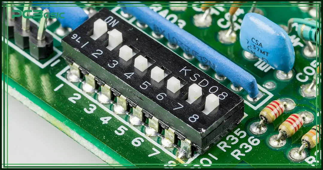
Although there are many new digital configuration methods today, DIP switches are still widely used because they are simple and reliable.
Computer Motherboards and Expansion Cards
In early personal computers, DIP switches were used to set hardware parameters such as interrupt requests (IRQ), DMA channels, and memory addresses. Today, most computers can configure these settings automatically. However, some embedded boards still use DIP switches to fix hardware settings and keep the system stable.
Industrial Automation and Factory Equipment
In industrial equipment, DIP switches are used to set sensor thresholds, select controller operating modes, configure servo drives, PLCs, and temperature controllers, and assign addresses for industrial bus communication. These settings help the equipment work accurately as required.
Garage Door Remotes and Remote Controls
In early remote control systems, DIP switches were used to assign separate radio codes to prevent interference between remotes. Many garage door openers and ceiling fan controllers still use DIP switch address charts to ensure each remote only controls its own device.
Arcade Games and Gaming Equipment
In classic arcade machines, DIP switches were used to adjust game difficulty, set the number of coins needed, and control volume and display quality. Technicians could easily change these settings by flipping the DIP switches inside the machine.
IoT and Embedded Systems
In many embedded and IoT devices, DIP switches are used to set network IDs, enable debug modes or select different firmware versions during testing. This makes development and testing easier.
Test and Measurement Instruments
In devices like oscilloscopes, spectrum analyzers, and signal generators, DIP switches are used to select operating modes, voltage ranges, or test functions. Users can quickly adjust the device based on testing needs.
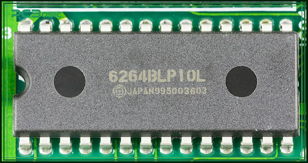
DIP switches are easy to use and do not need any software or drivers. They are low-cost and cheaper than using microcontrollers (MCUs) or firmware for configuration. Once set, the settings are very stable and will not be lost even if the power goes out. DIP switches control the device directly at the hardware level without depending on the operating system or software version. You can easily check the settings by looking at the switch positions. Unlike jumpers, DIP switches do not have small parts that can fall off, which makes them safer and more convenient.
To configure a DIP switch, you need physical access to the device, which may require opening the machine. For complex settings, you need more switches, so expansion is limited. It is easy to make mistakes when switching manually, so careful operation is needed. DIP switches are not good for settings that need frequent changes. They are better for fixed configurations. Because of their size, they are not suitable for very small modern devices.
DIP switches are very important components in electronic systems. They are simple, reliable, and low-cost and play an important role in many applications. Whether setting up industrial equipment, assigning addresses in communication devices, or adjusting parameters in embedded systems, DIP switches provide a cheap and useful solution without needing software control.
By learning how to read DIP switch diagrams, understand DIP switch schematics, and use DIP switch address charts correctly, engineers and technicians can easily set up systems that are efficient, stable, and easy to maintain.
Even as technology keeps advancing, DIP switches continue to be useful and play an important role in modern electronic devices.

Assembly Enquiry
Instant Quote
Phone contact

+86-755-27218592
In addition, we've prepared a Help Center. We recommend checking it before reaching out, as your question and its answer may already be clearly explained there.
Wechat Support

In addition, we've prepared a Help Center. We recommend checking it before reaching out, as your question and its answer may already be clearly explained there.
WhatsApp Support

In addition, we've prepared a Help Center. We recommend checking it before reaching out, as your question and its answer may already be clearly explained there.
